One other observation. This room has a decidedly horizontally polarized 60 Hz signal. Suppose it’s caused by the electrical service ran through three of the walls at code height.
Placing the QA high on the bench and dropping the test cables vertically to the DUT results in much lower 60 Hz interference versus the cables laying horizontal on the bench work surface.
The difference is rather dramatic.
Going to continue to experiment to reduce 60 Hz interference. Also looking at some double shielded STP cable where each conductor has it’s own shield.
@George_S what cable us that and where are you buying it?
Moto, a couple weeks ago I saw some two conductor Belden with a braid around each of the two conductors, but can’t find it now.
So, I just ordered some of this. I’ve heard it’s hard to strip and work with, but that’s OK. It’s STP with a double braided shield.
Did some testing this evening on a Acurus line level stereo preamp that is original and unmodified. It’s my bench mark. Very nice results from the QA using the single ended/differential cables.
I just want the best cables I can make, and get the best results.
1 Like
Thx for the reference.
I’m working with the cable today. Looks to be good stuff. The piece on the left is a test piece. It solders easily and the insulation is heat resistant. I’ll make up a couple sets and update if it’s worthwhile.

I’m very happy with the completed cables. They’re very labor intensive to make, but worth it I think. I made 4 single ended/differential and 1 fully differential loopback. I’ll go with these and pursue testing another laptop as the Lenovo T410 does produce a small 60 Hz spike on battery.


1 Like
Way back in time, I asked Matt on this forum about some hum artifacts. He offered some good suggestions which I followed up on.
But, in addition, what I found out through not just theory but practice might be helpful here.
-
Shielding pretty much does nothing for these low frequencies, especially 50/60 Hz. Because of skin effect, no reasonable thickness shield on a cable really helps. Matt suggested a mu-metal shield, which worked, but is kind of unwieldy.
-
You really need twisted pair or quad cables to minimize pickup. That’s true whether you are using a balanced connection or not.
-
Very often the hum source is an external device, like a transformer, whose magnetic field is too big for its britches. I had a power filter with an internal isolation transformer causing this. It didn’t matter what was plugged into it, either. Even with nothing plugged in, it caused hum. When I unpowered it, the noise went away.
If physically reorienting the parts of your measurement changes the noise and hum level, you have pickup from something external.
Of course, that all is just my experience. YMMV and all that.
2 Likes
Thanks. I didn’t know about the shielding. I do know that thel BK Precision isolation transformer sitting on the bench is a big offender. Found that out before Matt gave me the hint about about interference direction finding.
I keep the equipment power strips turned off when using the QA. No difference in them being turned off or unplugged from the wall.
Also, that aircraft cable has a much tighter twist then the balanced audio cable I was using prior.
Found time last night to use my newly constructed single ended/differential cables on the Acurus line level preamp, my “standard”.
Very, very, happy with the results. My interference issues are resolved.
@George_S I ordered that cable. How exactly did you connect the shielding to the rca and the bnc connectors?
On the RCA’s, the shield and differential low wire gets soldered to the ground lug as the PDF I linked to early in the thread shows.
On the BNC’s, there are a wide variety of configurations made. Most BNC connectors are best used with coax. Slipping the length of shield over each wire simulates coax.
Then the fun begins as the BNC I had on hand, Amphenol 69475, need slight modification to work. The nut and washers hole needed slight enlargement to pass over the thick heat shrink I used, and the Teflon insulating spacers hole needed slight enlargement with a very small drill held with a pin vice, for it to fit over the copper center conductor. Wire stripping was done exactly per the Amphenol “Assembly Instructions -C25” document found online.
The short answer on how does the shield attach to the BNC depends on what BNC your using. On the 69475, the shield braid wires get folded back over the gasket, trimmed to length, then the braid clamp is pressed against the braid. Tightening the nut compresses the shield braid between the gasket and braid clamp.
You’ll have to adapt whatever connectors your using.
My high differential wire is designated with a red zip tie.
Hi @matt,
Just in case you are unaware, PI Manufacturing has closed up shop as of 7/21/2023 and the link in your Getting Started page is now dead. If you go to the homepage pimfg.com it redirects you to the following landing page with the “shut down operations” announcement:
— Leapmicro
I hope I am posting this correctly, since it’s my first (I think). I’ve read all I can find on differential-to-single-ended cabling regarding the QA403, and still seem to have an unanswered question, so hopefully someone can show me where I’m locked up here. My question involves shielding, and the - side of the differential outputs. I’ll deal with the inputs later, as they are at speaker level.
My application is HiFi at the moment, so I’m dealing with relatively high level signals that probably won’t much care about the absolutely best shielding and rejection. With that in mind, if I am understanding this correctly, the + output center conductor gets connected to the high side of the RCA input on the DUT. That being the case, I’d assume the + output shield, the - output high, and the - output shield, all get connected to the “ground” at the RCA input of the DUT ? Or are the shields just supposed to float, connected only at the BNC on the QA403, and therefore the center conductors of the + and - BNC become the high and ground at the RCA input to the DUT? I don’t know why I’m so confused about this, but there you have it. I’m a bit new to differential inputs and outputs, so that’s probably why.
Thanks!
Hi @BBTV, these are all very valid questions.
First, keep in mind all of the BNC shells on the QA40x analyzers are tied together. You can check with with your DVM.
And yes, you’d use the center of the L+ output to connect to your RCA input on your amp. And since a BNC to RCA adapter will carry two signals (L+ and the shell on L+), you have effectively connected the QA40x ground to your DUT ground with that connection.
Next, you need to connect across the load of your amp. Since you have the ground established, you needn’t connect another ground. So, you can take two scope probes in 1X mode and connect those from L+ INPUT and L- INPUT to your load. And leave the ground clips hanging or remove them completely.
That will give you a differential measurement of the load with a ground established at the input of your amp. A DVM from any QA40x shell to your DUT ground should show a short.
The differential measurement also lets you use a very high quality FDA opamp inside the QA40x (OPA1632) to suppress the common mode signals measured across the load.
The approach above will work on any amp output. Note that on some class D amps, the speaker outputs sit at a high voltage (usually half the supply rail–about 25V or so. Since both terminals are at 25V, connecting your speaker to the amp terminals works because the voltage is the same and no current flows. Only when you apply signal do the outputs diverge).
On more traditional class A or AB amps, the - terminal from the amp is at the same potential as the RCA shield input. In those cases, you can also just take a scope probe and measure across the amp, using the tip of the scope probe on the + output and the scope ground clip on the - output. But if you guess wrong (that is, the amp wants to drive the - output), you’ll ask the amp to drive into a short.
So, the differential measurement is really safe when measuring a new amp. It works with single supply push/pull class D, it works with split rail push/pull class D, it works with A and AB…
Do you know the amp topology you are looking at? Sometimes that’s not obvious. I have ground the minus output from a class D amp with a push/pull before I understand what it was doing. Luckily the protection circuitry of the amp tolerated my misunderstanding…but yes, it can be confusing.
Please ask some follow-up questions if still not clear.
2 Likes
With PI Mfg. no more, anyone found an alternative source of good short cables with BNC connectors?
Hi gvl. I bought these: https://it.aliexpress.com/item/1005003207782113.html?spm=a2g0o.order_list.order_list_main.5.23d63696SzKhb7&gatewayAdapt=glo2ita
they are cheap, there is a good choice on lengths but they are definitely good
2 Likes
Matt answered my question in a Nov 23 post that I missed. Thanks.
I’ll try replicating that today.
My high wire is connected to the RCA center, low wire connected to RCA ground, cable shields are connected to the BNC’s but not to the RCA’s. The shields end just short of the RCA solder connections and are covered within the RCA with heat shrink.
This seems to be the best configuration and is different than the few diagrams I’ve found.
Compared to single ended, I get very good noise cancelation in a noisy environment.
Been away for a while due to “life”, but recently retired and now have time.
this is a super interesting thread. I’m currently using the QA40x single ended with BNCs and Pomona 1/4" to BNC adapters but the 60Hz issues are making it very hard to get consistent tests from our 3 locations. (Enhancement request, digital 50/60Hz notch filter to remove 50/60 Hz from measurement request).
I wonder if differential to single ended is the solution. @matt Pomona makes a simple adapter for this that I use to do this on my Tektronix and Grass Valley gear, but alas your BNC connectors don’t follow that spacing - might be worth considering for the QA404 future product to keep that spacing.
Does anyone know an affordable (<$50) ready made cable for this?
I found these on Ebay. Close but not there, but the seller says he can make them the way we would need. I’ll report back - I get these are cheaper than we would want, and not perfect but might be good enough. Feels like ideal would to be to use Quad Star microphone cable so the pairs are wrapped together differentialy and not this, but we shall see.
Here are loop back results using various cables and configuration.
My work room is a very noisy environment due to my choices. High power WiFi, lots of test gear plugged in and on standby. Isolation transformer on bench. Big workstation streaming music to a large stereo system. Soldering and desoldering stations usually on. Etc.
I can turn everything off when I want to use the QA403, but it’s a hassle, and detracts from my enjoyment of the hobby. I don’t like to even unplug or turn off the WiFi on the laptop connected to the QA403.
This is in no way to detract from the outstanding performance of the QA403. It’s remarkable to be “in the bushes” at below -150 dBv. It’s a awesome device!
The units I’m interested in measuring at this point are 70’s Phase Linear stereo preamps. Very noisy in themselves. I could easily raise the QA403 input attenuation and block out the majority of my enviroments noise and get great preamp measurements. But, unlike my old QA400 (which has a reserved place of high status on the bench!), the QA403 has differential inputs and outputs.
So how best to utilize them with single ended RCA jack gear? What’s the best cable configuration?
All measurements were done at 0 dB attenuation, max FFT, 10 pass average which I find gives me better results in my noisy room as spurious noise is dropped.
Added note. A ground wire from the QA403 case to the wall outlet center cover screw (ground) completely solved a 120 Hz issue.
Snap on RF chokes on each end of the USB cable reduced the background noise “hash”.
The 60 Hz spike seen on the Differential Loop Back is a given and not a issue. I see it when walking away from the house with the laptop on battery. It’s either laptop generated or from the power lines that run nearby. Not a issue at all.
This is single ended, two single BNC/RCA cables joined with a RCA female/female connector. A 50 Ohm BNC terminator is on each of the 3 unused inputs.

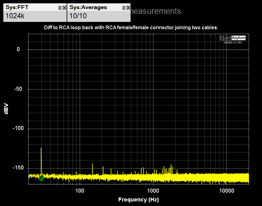
This is differential, two of the differential to RCA cables I made, joined with a RCA female/female connector. A 50 Ohm BNC terminator is on each of the 2 unused inputs.
This is the single differential loopback cable I made. A 50 Ohm BNC terminator is on each of the two unused inputs.

So, here’s the question to the Audio Engineers out there! How do we best utilize the differential outputs and inputs with single ended (RCA) gear?
Are cables with the high going to the RCA center, low going to RCA ground, and shield connected only to the BNC’s, a proper configuration?
And will we get a accurate results, or quasi accurate results.
Since I so hate crimping BNC and don’t really have time for DIY:
I talked to an Ebay seller and found these
Yes I know they are not wired ideally using differential cable but maybe they work better than what I’m doing. I got 2 pairs to try out and will report back.
I’ve also spoken to a higher end cable maker about doing these with proper star quad cable etc. He may have a nicer solution to offer us. I’ll post back if I learn anything.
1 Like