Hooking everything up to my Siglent scope and manually cranking up the frequency on the generator the level is linear until about 120k and slowly starts dropping.
Removing C2 and hooking the generator output directly to the grid doesn’t change anything.
What is wrong with my use of gear, that the graphs from the Velleman and the QA403 are going in different directions at the same point (1k) and the scope doesn’t show that rise/drop at all?
Thanks for any hints about how to properly use my gear!
If I understand your circuit you are driving the plate and looking for output from the grid with a current source on the cathode. Really its a measure of the capacitive coupling between the plate and the grid, which is all hi-z circuitry. You would hope to see very little at the grid because it would affect the utility of the device if there was much (unless you are driving into grid current).The different results are more a measure of the input impedance of your probes than the circuit. What were you expecting to get? Did you model the circuit and run the sim? The gain from grid to plate will be small since the cathode is fed from a high impedance which reduces or eliminates the voltage difference between grid and cathode, which is what modulates the current flow. I must admit I have never seen anything quite like this.
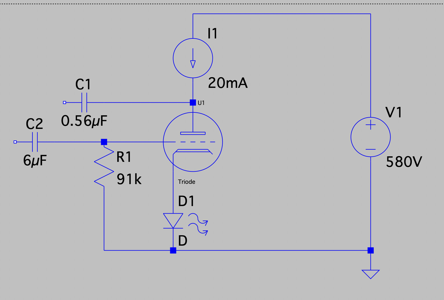
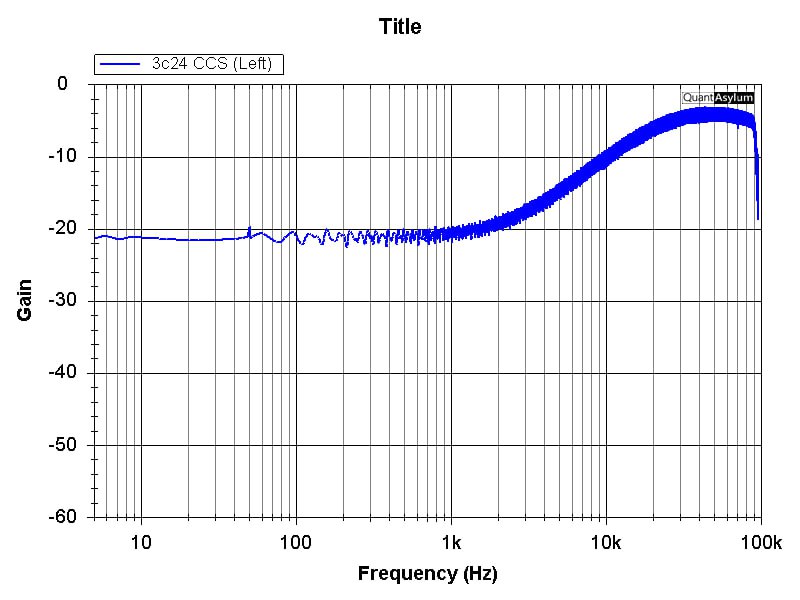
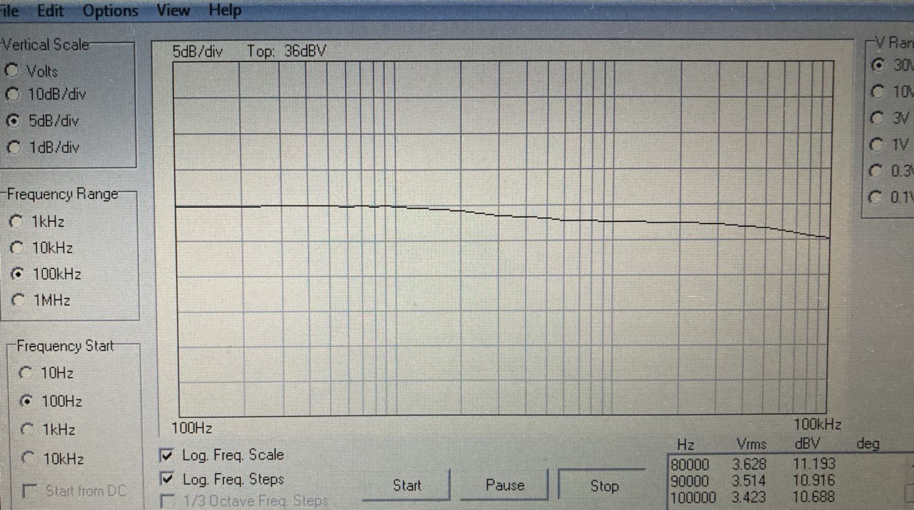
Hi, thanks for your input, maybe my setup description was too confusing. The generator is hooked up to the grid, the input of the analysers hooked up to C1. It’s a bog standard anode follower. What I was looking for was the frequency response with the CCS load. And I am baffled that with the QA403 the response rises from 1k upwards, with the Velleman it falls from 1k upwards and with my scope it rolls off much much later.
IMH correctly connected the output of QA403, the generator, to the grid through capacitor C2 or directly and the input of QA403, the analyzer, to the anode through capacitor C1.
Hi @THDaniel, the comments above are all good places to research. But keep in mind the scope input is probably 1M ohm while the analyzer is 100K. When in 1X mode, the probe is a wire. But when in 10X mode, the probe is a 9Mohm resistor. Are you sure what you are seeing isn’t a resonance formed by the probe and the QA40x input? Note that the trim pot on scope probes doesn’t do anything in 1X mode, but when in 10X mode, they do. And so, if you’ve not trimmed the probe correctly to the QA40x input, you might be introducing some peaking.
Something to try when measuring wih the scope probe in 10X mode on the QA40x–turn the trim pot and see if anything changes.
So, two things to think about: The amplitude (and noise) issue that comes from inserting a 9M series R with the analyzer. And the resonances that will form given the combination RLC from your setup.
Good progress. The current source in a “common cathode” will reduce the gain a lot, to potentially less than zero. A current source in the anode will get the most gain possible. However the current source needs to handle 400V in your example. Its been decades but I remember the tube is most linear when it has around 100V anode to cathode.
The current source in my example is able to handle 900V. There is a myriad of valves, some of which are their linear region at around 100V. The speciman I am dealing with here was intended to run with an anode voltage above 1kV and up to 7W at the control grid…
In my actual use case I am looking for 600V anode to cathode 35V drop across the CCS to deal with the swing.
900V compliance in a constant current source is quite difficult to get. I would like to see more. Still, having the current source on the cathode should yield effectively no output on the anode. It would be a cathode follower in effect.
I have the current source on the anode. Bias dials in the anode voltage/voltage drop across the CCS which needs to be set for a minimum of necessary operating voltage drop across the CCS plus half of the swing.
The 900V is not that big of a deal. I use a cascode of 10M90s top and DN2540 bottom. 1k gate stoppers and TVS diodes between gate and source.
Now I understand what you are doing. My one real suggestion would be to do the following; Get an X100 scope probe, preferably: vintage untested Tektronix P6009 probe with screw on 013-0071-00 tip 6Ft.#46 | eBay and build an X1 buffer with 1 Meg input using any of a number of opamps. The vintage Tek probes offer better safety keeping the operator further from the HV.