Found that my soundcards Creative E-MU 0204 and Tracker Pre emit residual waves in a out-of-band frequency region, around 100 kHz and higher. Since I work also with analog measurement instruments which go up to 1 MHz bandwidth these residuals distort low signal measurments. Is the QA403 much better in this sense?
Greetings to Matt,
Sven
Germany
Hi @Sven, the QA403 uses a ES9038 DAC, and modern converters are eons better than the converters popular 15 years ago. But, that said, I don’t think I’ve seen any ES9038 measurements out to 1 MHz–not even from ESS Tech. If you have that equipment and want to measure, I’d be curious to see. If it doesn’t meet your needs, of course we’d take it back and refund you the purchase price. And in your case, if you can post the measurements, any shipping + VAT + import fees + return mail fees you experienced.
What would you measure with? AP555B?
Hi Matt,
no, I can’t afford an AP. Have several meas tools like Sennheier UPM 550 which is an analog pointer instrument special audio measurement tool which goes to 1 MHz with 1 mV FS and up to 100 kHz FS range is -90 dB = 30µV. Also I have a Sound Technology ST 1710A which measures up to 100 kHz -80 dB FS which also my HP 8903B can do. For time based meas I have the HP 54616C scope which can go up to 500 MHz. I am an retired old school hp EE who has audio as a hobby and restores mainy electrontube based gear. Will try to get a QA403 from Elektor, but currently out of stock.
Hi @Sven, I’m pretty sure the out of band noise of the QA403 will beat all of those devices. In a 20 kHz bandwidth the ADC noise is about 1.3uVrms, and in a 95 kHz bandwidth it’s about 3.5uVrms. There could be some nasty stuff lurking up above 100k, but hopefully not enough to get to the level your UPM550 can measure.
Hi Matt, thank you for the information. Of course the performance values of the QA403 and other DACs today are better than my meas insturments. Since I do not develop 0,0001 % THD amplifiers it is sufficient when the DAC is so good not noticeably show up spuriious signals on my instruments which measure down to approx. 0.002 % THD. When will the QA403 be available again?
Hi Matt, got my QA403 yesterday and made some tests today. At all outputs and 96ks/s and 196ks/s settings generator level -150dB there was out of band noise as spurious signals. One is around 500 MHz sine like and then many super short spikes with 0.2 ns distance bunched and repaeted every 250 ns. Peak voltage read on my analog Sennhieser 10Hz-1MHz bandwidth is 2.7 mV. Tried both with a USB hub and without a hub directly to the Windows PC. Maybe I need a RF filter to get the stuff away. Futher noticed that in RUN mode the generator output signal is repeatadly stopped for 40ms. When STOP set and IDLE set the signal is in continuos mode. What happens here? Found in the Manual that is done during measurment, but why? My audiotester software with the EMU Tracker pre does not do this. Regards, Sven
Further THD test with my ST 1710A at 1 kHz 1 Volt shows a minimum distortion of 0.035 % when not band limited. Limited to 80 kHz it is 0.001 % and limited to 30 kHz it is 0-00075 % which is somewhat the lower limit of the 1710A. So any QA403 residual noise out of band is influencing the measurement. Seems a RF filter at the output is needed.
Interesting investigation Sven. ![]()
Thank you. May be it is out of topic for most normal measurements.But I live with and like analog meas instruments. They show really what happens way out of sample rates bandwidth and measure really the voltages and frequencies.(f-meter of course digital). Reason for all this is that I will use the QA403 in conjunction with my other insturments, also in order to validate readings.
By the way, in ASR I am under SSS.
Not to be wrong understood I want to express that the QA403 is an excellent well built instrument which I like to use. My findings are not to critizise the unit itself.
Hi @Sven, the QA40x guarantees the phase relationship between ADC and DAC always. A sound card doesn’t usually have this guarantee. Part of that guarantee requires that they outputs operate in a bursted fashion while making measurements. At some point, there will be an option to run continuously without a phase lock between acquisition cycles.
The analyzer has 100 ohms output R in each leg, so if you put a 10nF across the outputs, that will form a cutoff at 100kHz (20 dB atten at 1 MHz). And a 100 nF at 10 kHz, etc. Very easy to try.
You noted a sine at 500 MHz. Did you mean 500 kHz??
Hi Matt, thank you for the explanation regarding bursted mode. Makes sense.
It was according to my oscilloscope 500 MHz. Could not directly measure the frequency. It was calculated from the period 2 ns. Of course hopefully that my scope did the display right. But it is a 500 MHz digital scope from hp. So I think it schould be so. Yes, a simple solution is of course your proposal. For normal measurements of amplifiers it is not necessary. It is just when verfiying my other meas instruments with the QA403. Did run some tests also with 3rd party software (ASIO401 driver) and this works well too. Great meas tool is the QA403, lucky that I bought it.
1 Like
Hi @Sven, next time I am at warehouse I will try to remember to capture plot of output on RF spectrum analyzer and report it here. It’s a good experiment to do and I have never though of doing it before. Please continue to report results if you take more measurements.
Hi Matt, great idea. Would like to know whether my findings are not only on my specific QA403. Unfortunately I don’t have a RF spectrum analyzer since I do not much on transmitters and receivers, just only repairs and some restorations of old tube based radios and amplifiers.
1 Like
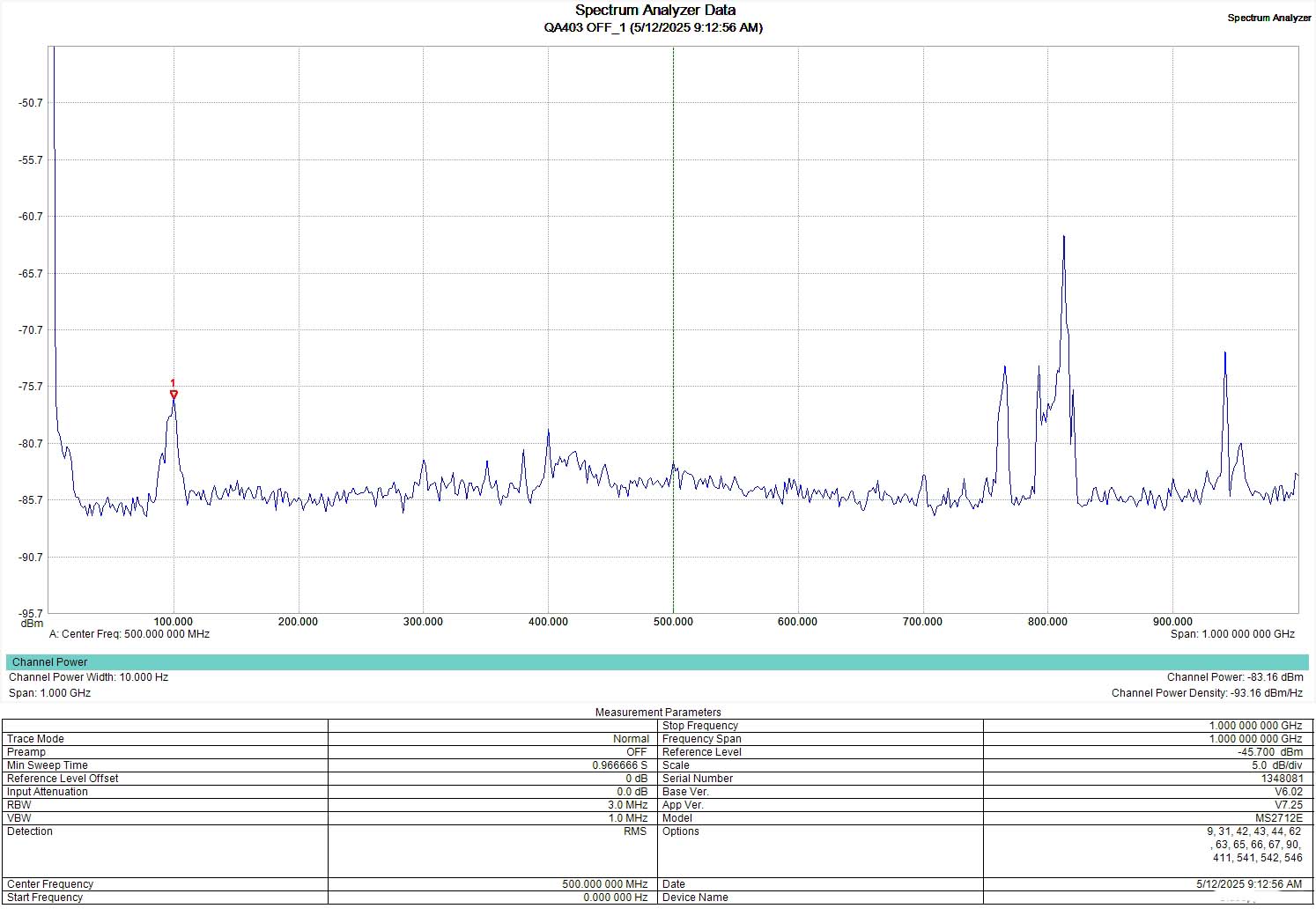
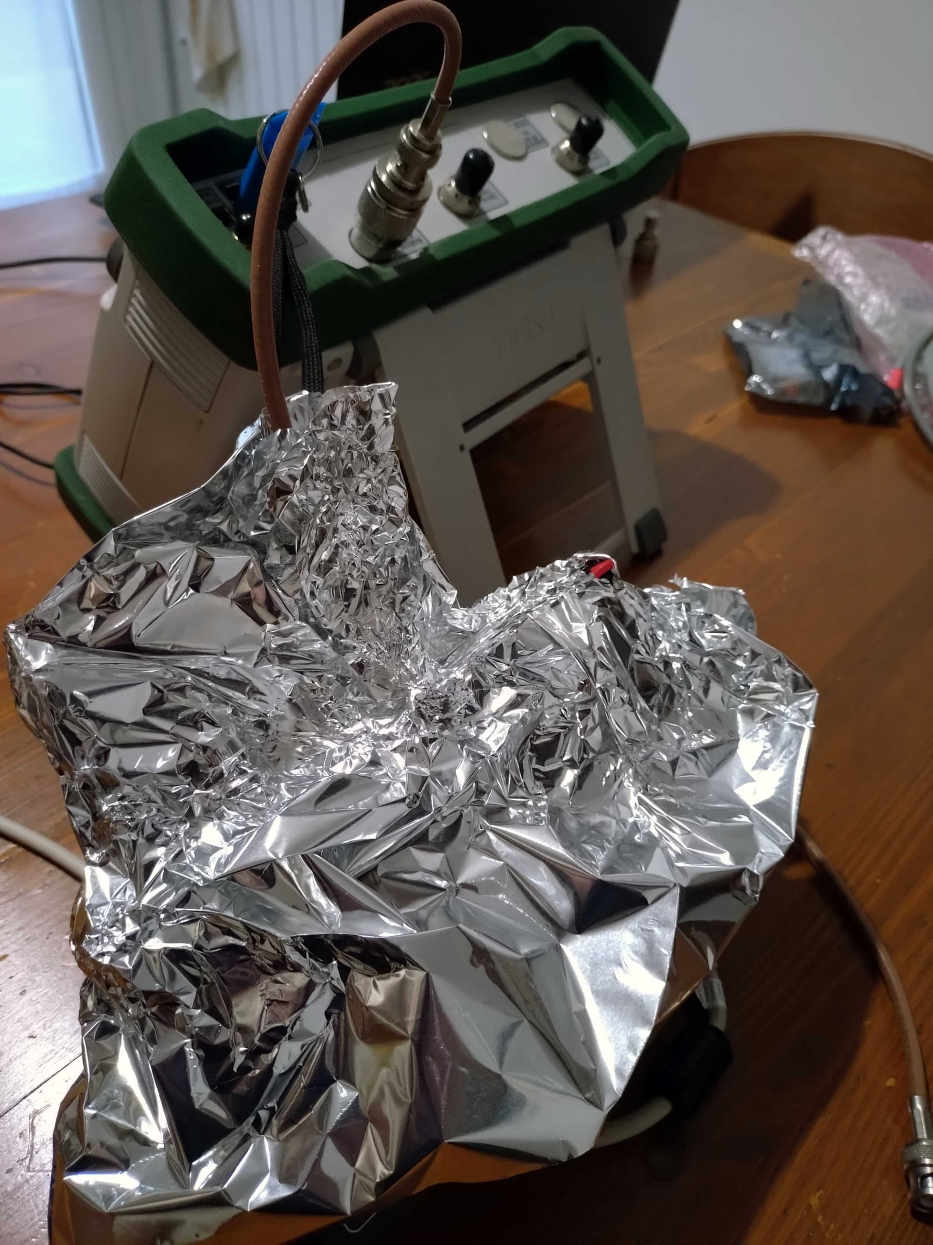
Hi, I had the chance to do some tests with my spectrum analyzer and I share them with you. I used an aluminum foil and also a 10 Mhz low pass RF filter. Below are the images:
image 1: QA403 off connected to Spectrum Analyzer.
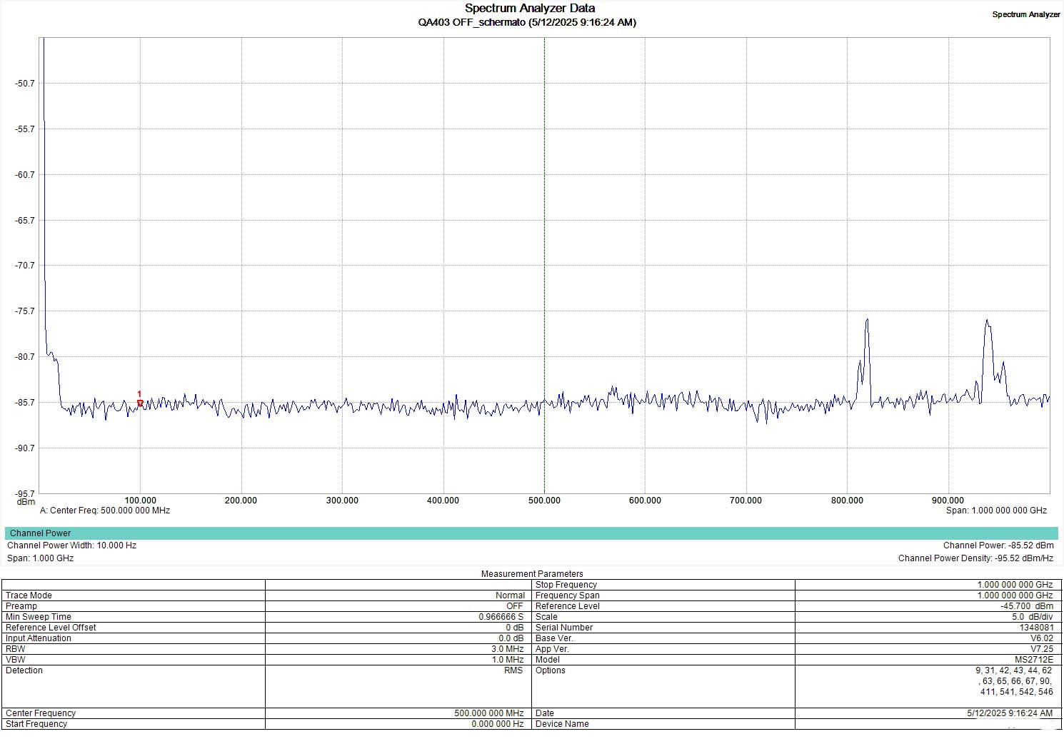
image 2; QA403 ON with Spectrum Analyzer (Note how the QA403 acts as an antenna and picks up signals).
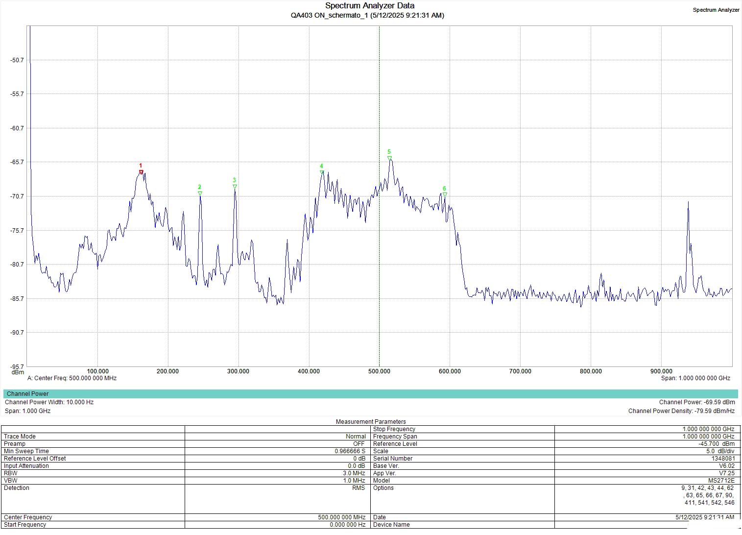
image 3: QA403 connected as before but with an aluminum sheet acting as a shield.
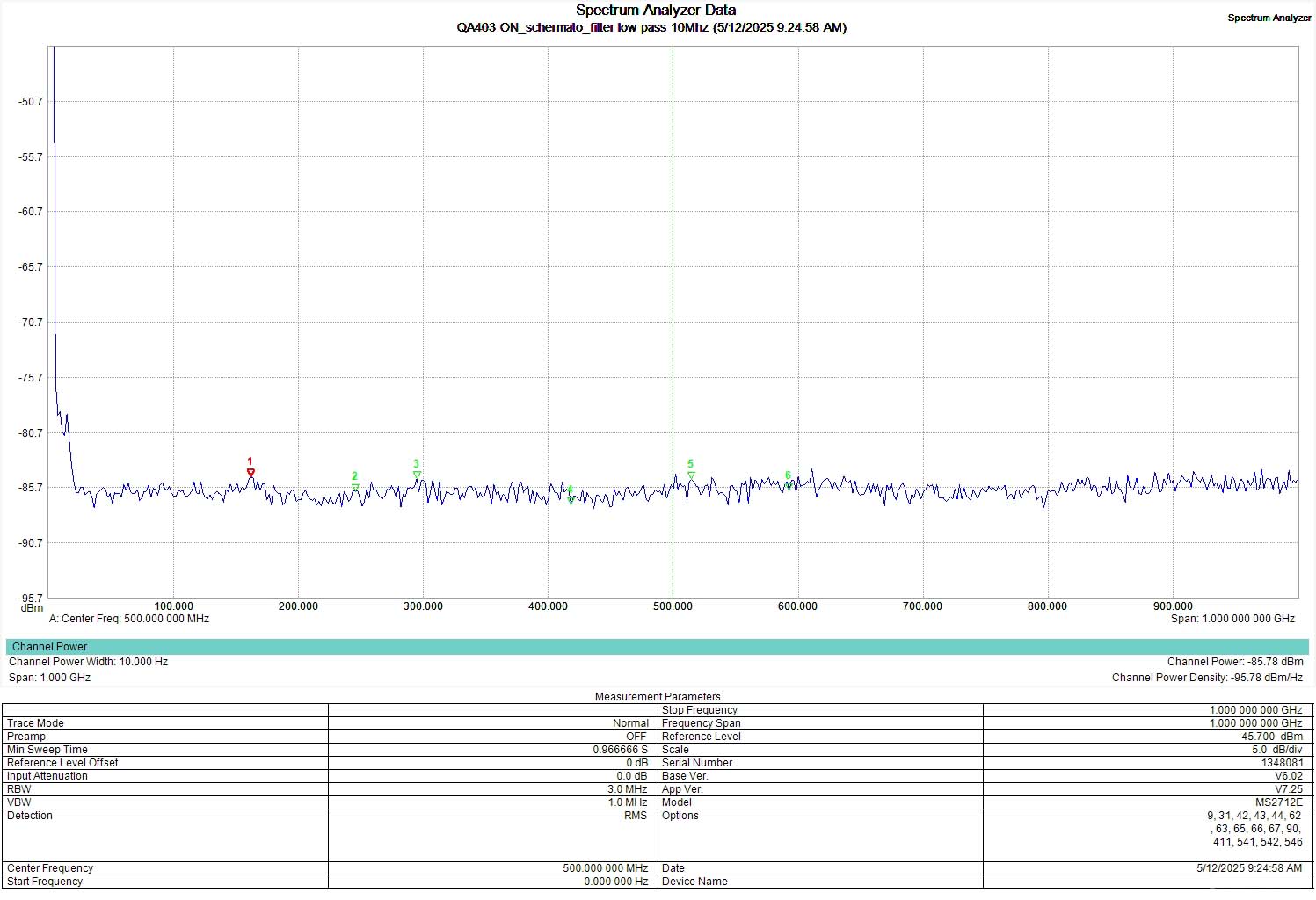
image 4: As before but with a 10Mhz low pass rf filter.
image 5: the aluminum sheet covering the QA403.
Guiseppe, you have 5 claimed results and four plots. What is what? Makes no sense.
Hi John, there are four graphs and the fifth image is the aluminum foil that shields the QA403. The four graphs respectively represent the QA403 connected but off, connected but on, connected but shielded with the aluminum foil and the fourth graph with a 10Mhz low pass filter. You can see that the QA403 turned on actually generates signals around 500Mhz as reported by Sven. If you are careful to shield or put a low pass filter everything becomes acceptable. What is not clear to you? Forgive my English but I hope I was clear.
HI. Good job, but I think “image 2” is not the one represented because it is indicated: “QA403 OFF” and not “QA403 ON”
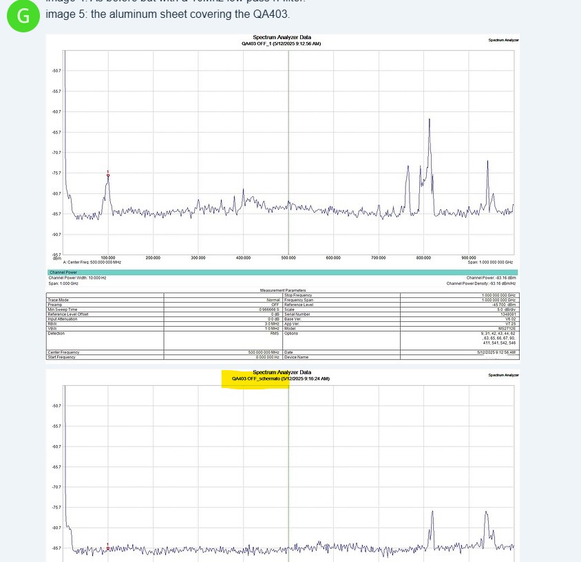
Hi Claudio, you are right. the second image is off but with the aluminum foil shielding. Thanks for highlighting it.
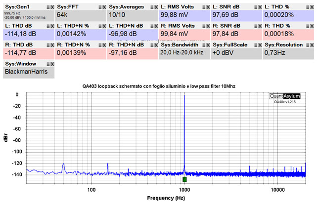
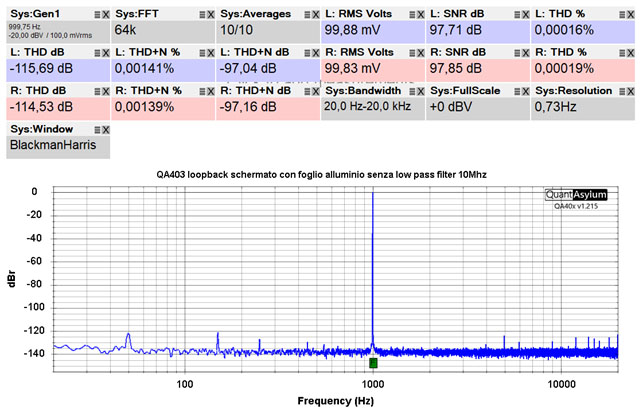
I wanted to add two measurements made with the QA403 in loopback, with and without the low pass filter to highlight any decay in the audio band.
Hi Giuseppe,
thank you for the tests. For me it is not clear whether the QA403 creates the ~ 500 MHz signal by itself or is it introduced from outside and then presented at the output terminals? Of course a simple filter at the outputs will cancel the RF signals. Loopback at my unit up to 50 kHz did not show any bad signals like your chart does not show it. Maybe Matt could evaluate the VHF signals further.