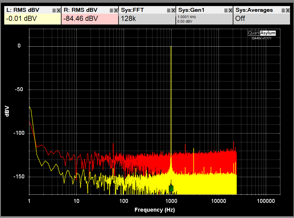
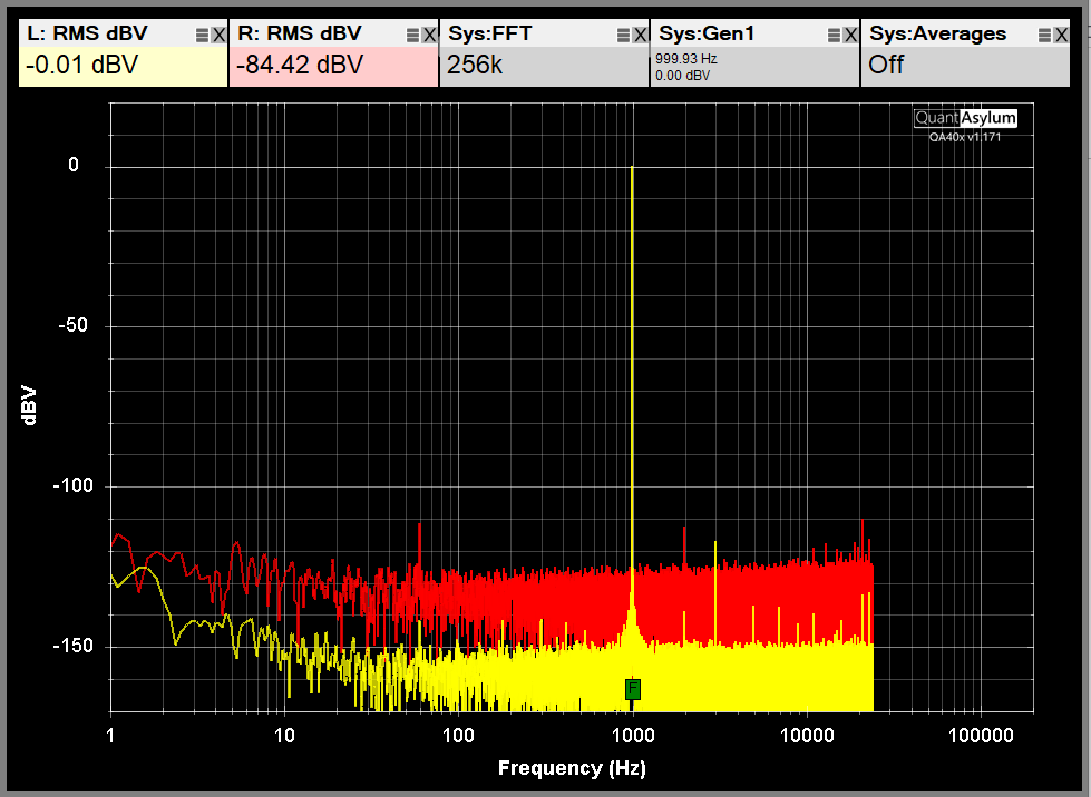
It looks that I get strong dc component on both channels. Is it possible to get rid of it? Or maybe implement the button that will do subtracting the mean, then multiplying the data with a window function, and then zero-padding
Hi @dimitri, just to check, the energy shown from 1-7 Hz or so is where the DC shows up. Are you referring to that, or are you referring to the 30 dB difference in the noise floor out at 10 kHz or so?
The noise floor depends a lot on the input impedance presented to the amplifier, and also the full scale input range.
The check things are function as expected, disconnect all the outputs from the analyzer, and short the four inputs with 0, 50 or 75 ohm BNC shorting blocks.
Then select File->New Settings to put the analyzer into a known state. Then select the 0 dBV full scale input, and then adjust the FFT size to 64K, and then press the RMS measurement button to get a 20 to 20 kHz RMS reading. That should appear similar to below. Please share your screen shot.
Now, if instead you were talking about the energy below 7 Hz or so, that might be something to address. The DC offsets are tied to the attenuator settings and also the full scale input range. There might be a user-calibration where you short all the inputs, let the analyzer make some measurements, and from that the DC offsets will be determined for every input range. And then measurements in the time domain will show true-zero. The fact that there are DC offsets are an annoyance with plug-in (like the experimental scope plug-in) where you expect to see a DC offset of zero. In any case, it’s a flagged work item.
Thank you, Matt. hf difference in the noise floor is caused by the different termination - yellow input is terminated by the oscillator, red input is terminated by 2x1MOhm (internal). If I terminate red channel inputs with shorting caps I get the same noise floor for both channels
The DC offsets are tied to the attenuator settings and also the full scale input range.
I assume that you used JFET input op amps with the low input, and output dc offset may be tied to the gain setting, correct?
Before FFT you may subtract the mean from the original signal or apply a high pass filter to the original signal.
Hi @dimitri, that is good news! In general, I think you need to keep the input terminator in place when you are operating in single-ended mode. The input Z is 100K ohm, and the input opamps are OPA1612. These have bipolar inputs and are very low noise. But without the termination, you have 100K resistor noise married to the input current noise, and as you can see that combination can degrade the normally quite-good noise. So, termination is important for most measurements.
Thank you Matt, now I understand why DC offsets are tied to the attenuator settings


