Matt
I have been playing with Mark Z’s QA40xPlot and doing most of that in loopback.
This is when I found that my QA402 does not meet its THD spec as per the Product
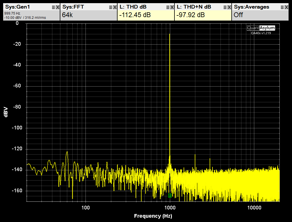
Brief: -110 dB (loopback, single-ended, L- shorted, -2 dBV input, 128K FFT, Hann window)
I am getting in the area of -92dB THD with these settings.
I started to look at “everything”…USB Hub, Cables, Appliance electrical interference,
Neon lighting, Processor Power, RAM. I Ran the tests on 3 different PC’s, 2 with plenty
of horsepower and less than a year old and one with “enough” horsepower. One of the PC’s
was even in someone elses house (Who runs a 401) 10 blocks away so all different cables,
power supplies etc. All had basically the same results (within a dB).
Then I ran the QA40x Verifying Calibration found in the QA40x Wiki. Steps 1 & 2 ran fine.
Step 3 gave me exactly 1.000V RMS at 60Hz and 1KHz on all 4 outputs (+ & -) with a Fluke 87V.
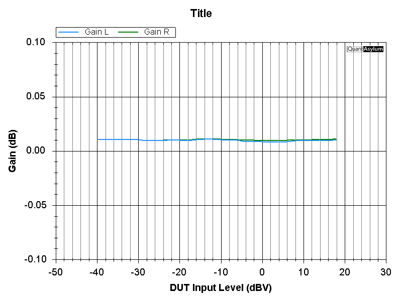
Step 4 (Verify Relay Gain Ranges) is where I saw some odd results. Traces attached.
Any ideas what is causing this? Is this normal. Is this repairable? Mine is an early 402
(July 2021 Order# 217921A) I CAN get -110dB THD but only at -18dBV. I almost always run my
testing at Line level (-10dBV). I have tested a few power amplifiers but nothing over maybe
70W. Very conscious about DC.
Duh, I just figured out. I didn’t do the zoom in on the graphs. When zoomed in they’re flat like the examples in the wiki document. What clued me in is I’m actually running a test on a power amplifier today, and I did the same amp gain and Distortion versus amplitude test. The result was fairly flat running through all the relay stages. I went back and ran the verifying calibration again and saw what I had done. Thanks
HI @BarryLambert, something does look up with your THD. If you look at the Product Brief for the QA402 on page 5, you’ll a measurement at -10 dBV, and you can see the spectrum there along with the settings. Can you replicate and show that plot?
Hi @BarryLambert, yes, the THD figures on the QA402 seem very degraded. The 60 Hz could be environmental. If you make the noise measurements shown on page 4 of the product brief, does the 60 Hz go away? If you rotate the device around in free space, does that change your 60 Hz levels? There can be a lot of ways the 60 Hz is creeping in, and it’s probably something on your bench that is coupling in.
Does the right channel exhibt the same THD? What is shown on the screen is L+ input with L- input shorted. If you flip that and loopback into L- and short L+ does it show the same? And then use L- and R+ and R- OUT and see fi the levels change?
it’s not clear yet if the excess THD is coming from the generator or ADC. But swapping the inputs and outputs should help you determine. Please report back when time permits!
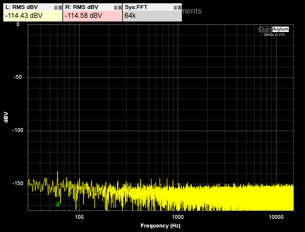
Re: If you make the noise measurements shown on page 4 of the product brief, does the
60 Hz go away? - NO
If you rotate the device around in free space, does that change your 60 Hz levels?
YES, some orientations are worse. Others no change.
If I run off a battery powered laptop on the floor above the shop, it is gone. Laptop
in the shop it is present.
Turning off ALL electrical appliances and lights in the house made no difference.
I had to turn the shop (basement) lights off at the BREAKER to get rid of it. It is
the routing of the wiring that is causing it.
Re: Does the right channel exhibit the same THD? Essentially Yes
Ran loopback L+ input with L- input shorted then from L- (L+ shorted). Essentially the
same.
Eventually ran all possible loopback combinations. Little difference
Some of those combinations are posted below.
The other lowest distortion signal generator I have is a Sound Technology ST1700B.
In loopback it can do ~ .001% or ~ -100dB
Ran ST1700B -2dBV OUT (@ 1KHz) to QA402 Left+ IN getting .00213% or -93.5dB.
(so similar to the 1700B itself)
Ran QA402 Left+ OUT IDLE (@ 1KHz) to ST1700 IN at -2dBV and got .05% ~ -66dB
So even with the inputs shorted you are still seeing powerline? Can you share a plot of that?
If I run off a battery powered laptop on the floor above the shop, it is gone. Laptop
in the shop it is present.
What if you run from a PC (older tower style) that has a solid earth ground? OR, connect the input shell of the QA402 to earth ground via something like this. These grounded outlets let you plug into any wall plug and then you get a alligator clamp to bring the ground wherever you want, making it easier to debug these types of issues.
If you have ever looked at the “ground” on a two-wire laptop charger, it’s not silent. I can be swinging a strange 50 or 60 Hz waveform some tens of volts in amplitude.
In any case, can you try to get a solid ground on the BNC shells and confirm that when inputs are shorted the noise is tamed? We first need to understand the power line issue. Note that for 50/60 Hz there’s not much shielding can do until you get to more exotic materials like mu-metal.
You can also send this in if you’d like and we can check. If you want to go that route, contact Jan at support.
Another d u h on my part. That’s a couple this week. Rereading the product brief, I had not shorted the inputs for the noise test. With shorted inputs, 60 HZ is down around -144 DB. I had also been experimenting with grounds running in loopback during all this. I would probably get a 403 rather than send this in anyways. Any idea of the time frame before a 404 comes out? I will be out of town for a week and will look at this thread when I return. Thank you very much for all this.
Hi @BarryLambert, it’s great it’s working! I have had some “duh” moments too measuring some of the more esoteric Class D amps such as TPA3255, balanced versus unbalanced, etc. The things we’re looking for are very, very small in magnitude, and the setups need to be just so to reveal the issue. And it’s how we learn and get better as engineers and techs and hobbyists.
I’m pretty sure the QA404 won’t be anytime this year.
Thanks for the reply. I still have the Distortion issue mentioned in the original post. I’ll be home next week and I will have access to a QA 401 to use to compare to my 402. It will have a lower Distortion signal generator, I think the spec is 108, and I’ll see if my 402 can measure it. Then I will measure the signal generator from the 402 on the 401 and see what the results are. The 401 will run on my usual desktop and the 402 will run from a battery powered laptop. Then we should have a better idea whether it’s the DAC or the ADC at fault.
I now have a QA 401 and a 402 on the bench. The 401 meets its specs and then some , I’m getting - 110 DB THD in loopback . Hopefully I will be able to determine what the THD issue is with the 402. The 401 can easily read the 402 when the 402 is in idle. Is there any way to sync these two devices so that I can read the 401s pulsed output on the 402? I have also been following the out-of-band noise thread with interest as I have a sound technology 1700 B so have ordered that same LPF. I was also getting poor results from my 402 on the 1700b and was wondering why . Will be posting results later in the week. Thanks
I just spent the last 2 hours running tests on a QA 401 QA402 and an ST1700B. Then I saw this post. I just ran it as per Matt’s instructions. I’m getting the same readings. Unbelievable. An hour ago I was getting in the area of 91 to 93 DB . Nothing changed. Same computer, same cables. And now it’s working properly. I just added in the right Channel and it’s the same thing. Better than minus 110 DB. I’ll post all the rest of the stuff I did earlier tomorrow. But right now it all seems to be working correctly and that makes no sense to me based on what I’ve been experiencing for the last couple of months. What I am going to do is let this run for a few hours and see if it changes, deteriorates. Who knows. But I was not expecting this. Edit, 5 minutes later. Found it. If I switch to zero dbv full scale input I drop to - 95 DB. I almost always run at line level, minus 10 DB so I usually have no attenuation on. What do you make of this? At this point I don’t think I need to post all those other traces I did earlier today. Thanks
I @BarryLambert, I think your first issue with the 60 Hz kind of clouded things because it degraded the distortion (or appearance thereof). And then once that was fixed, the issue was one of selecting the full scale input. If you leave lots of headroom (eg 0 dBV input and 24 dBV full scale input) you’ll optimize for THD, where as if you leave very little headroom (-2 dBV input and 0 dBV full scale input) you’ll optimize for THDN. And so, it sometimes takes a bit of hunting on setting the full scale inputs to arrive at what you want to see. It’s the same with an RF spectrum analyzer too. You must optimize for noise or THD, and they aren’t always the same setting.
One thing that might be helpful is to plot THD and THD+N versus input level, and do that for the various full scale inputs (that is, don’t let the analyzer manage via autoset). And then print that plot. When you are looking at a signal, it’s a quick way to see where you might want to be given the input signal level for both THD and THDN.
Thank you for the response . I do understand what you are getting at . But in the test above, the input level is minus 10 dbv so there is more Headroom than at -2 dBV. Could you please post the results of the 402 that you have on your bench with no attenuation and -2 dBV generator level. Edit 1… I ran a whole bunch more traces and I’m starting to see what you’re talking about. I’ve been using these devices probably for about 5 years amazing what I don’t know. I think the thing that happened here was that I assumed that the THD figure in the product brief was arrived at with zero attenuation. When I run a Trace with the same settings as your Sample UI example in the product brief, -10 dBV @-12 DB full scale input, the only screenshot that shows the entire interface therefore showing the FSI setting, I get exactly the same results. Edit 2 - Just read Bob Cordell’s Analyzer THD vs FSI Margin in his QA403 Tutorial v4. This explained it. Thanks