QA472 Measurements

QA472 Mic Preamp Analysis

The QA472 is an upcoming mic-preamp product to replace the QA471. The QA471 was based on an SSM2019, while the QA472 is based on the INA849. The INA849 offers much tighter gain limits, improved THD, and similar noise performance as the SSM2019. The mic pre offers, 0, 10 and 20 dB of gain, which are selectable using a front-panel button that cycles through the gains.

The QA472 also has an ultra-low-noise JFET amp with 30 dB of fixed gain.

The purpose of this post is to show how to make the measurements to characterize a mic-preamp. As the product being evaluated here is preliminary, certain specs may change prior to shipping.

QA472 Front Panel

The front panel of the QA472 is shown below.

PRE1: Mic Pre

From left to right, there are indicators for Power (the QA472 is powered by USB) and also +48V phantom. PRE1 has both BNC and XLR inputs. A push button to the left of the BNC will enable system phantom generation (+48V). To the right of the BNC inputs is an input select button, and LED indicators for BNC or XLR inputs.

To apply Phantom Power, the +48V button must be pushed and held for 1 second. To turn phantom off, a momentary push is needed.

Phantom is never applied to the BNC inputs–only to the XLR inputs. When you switch from XLR to BNC inputs with phantom power active, the phantom will be turned off and a short “bleed down” delay will be imposed before switching to the BNC inputs to ensure the full phantom voltage isn’t applied to whatever you have connected to the BNC inputs.

The XLR female inputs do not have 1/4 TRS, but a push-lock tab is provided. To the right of the XLR input is the gain select button, and LEDs to indicate the selected gain. And finally, a single-ended BNC output.

PRE2: JFET Pre

The JFET pre-amp is based on the TI JFE150 “ultra low noise” audio N-Channel JFET. This part has the ability to deliver noise performance about 5-10 dB better than the OPA1612 opamp with low (<1K) source impedances. And 20-30 dB better noise performance with higher-Z sources.

The QA472 front-panel settings are remembered through power cycles. So, if the QA472 is part of a measurement setup, a power cycle will restores the measurement settings you had in place. The QA472 is not USB controllable.

The measurements below were performed on REVC boards, with mods made that will be reflected in a REVD board, and REVD is expected to go to market.

Measuring PRE2: JFET 30 dB Preamp

JFET Amp Gain

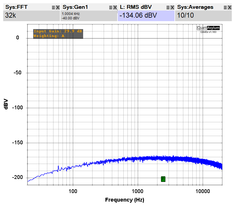
A first measurement we’ll make of the JFET pre is the gain, because we’ll need to know this number for the “referenced to input” (RTI) noise measurements we make next. With the QA403 L+ output connected to the PRE2 Input, and the PRE2 output connect to the QA403 IN+ (and with IN - shorted), we can make a gain measurement as shown. Note that with 30 dB of expected gain, we’ll set the generator to -40 dBV.

Above we can see the amp delivering 29.89 dB of gain. This is a “no cal” amp design based on the TI app note for the part. TI’s overall circuit is a hybrid, using a JFET front end, and a precision opamp to close the loop. More units need to be measured to understand the spread of the JFET amp’s gain. But initial looks show them to be fairly tight and in good agreement with spice.

JFET Amp Noise

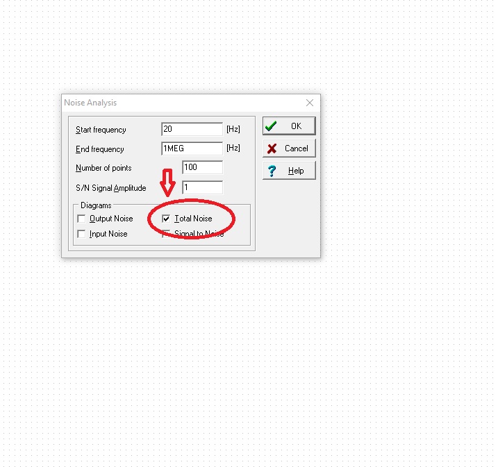
With the gain known, we can short the input of the amp. Because this amp is high-gain and also very low noise, it’s important to short the amp input with a true 0 ohm shorting block instead of the often used 50 or 75 ohm shorting block. Below we can see the thermal noise in a 20 kHz bandwidth of various resistor values. For example, a 120 ohm resistor normally has a thermal noise (in a 20 kHz bandwidth) of -134.03 dB. And with 30 dB of gain, we’d expect that to result in an amp output noise of -104.3 dBV. As we’ll see below, with this gain and noise, even a 120 ohm resistor will degrade the performance of this amp.

image

With the input shorted, we can see the A-weighted spectrum:

If we replace the 0 ohm shorting block with a 75 ohm shorting block, there’s about 1.5 dB of degradation:

The QA471 had a 30 dB amp based on a OPA1612 low-noise audio amp. The RTI noise of the OPA1612 is -129.42 dB. So, the JFET delivers about 6 dB better noise floor over the OPA1612. And as the source impedances increase beyond 1k, the JFET performance will get better and better due to to the current noise in the OPA1612.

JFET Distortion

Below is a sweep of input level versus THD. We can see at -20 dBV input (10 dBV output) that clipping is starting to occur.

Looking at the spectrum with -40 dBV input we see the 2H is about -105 dB below the fundamental.

Note the THD+N is -84 dB, which is considerably worse than the THD. We can see the N-D (noise minus distortion) is -94 dB. But now, let’s short the input again with a 0 ohm shorting block. Note the N-D figure improves about 10 dB, which means the THD+N is limited by the noise in the output of the QA40x analyzer, not the preamp. From this, we can roughly estimate the THD and THD+N are both about -103 dB at -40 dB input.

JFET Frequency Response

The plot below shows the frequency response of the JFET amp. The amp is bandwidth exceeds the bandwidth of the QA40x in 192Ksps sampling rate.

In the next week or so, the mic preamp measurements of the QA472 will be posted. The last board had some stability issues related to excessive capacitance due to switching topology on the INA849 gain setting resistor that will hopefully be resolved in the next board pass.

1 Like

Measuring PRE1: INA849 0/10/20 dB Preamp

PRE1 on the QA472 has both BNC and XLR inputs. The XLR inputs can be connected to the 48V phantom via 6.8K resistors, but the BNC inputs cannot. Because the large 6.8K resistors, the phantom voltage isn’t a threat to the either the inputs or outputs of the QA403. This is because the 6.8K resistors will limit the current to about 5 mA or so. So, you can freely plug any of the inputs or outputs on the QA472 into the inputs or outputs on the QA403 for short periods without concern for damage.

INA849 Gain Tolerance

There are a lot of choices for mic preamps, including the SSM2019 and THAT1510. And all are great for noise. Where they fall a bit short, however, is gain tolerance. The SSM2019 allows you set a fixed gain with a single resistor. And for a gain of 10, you can see the from spec sheet below that the typical gain error is +/-0.2 dB. But it could be as bad as +/-0.5 dB.

And the THAT1510 is similar in that the gain error can be as much as +/-0.5 dB:

Now, when you are offering the user a constant gain range from 0 to 60 dB via a pot, the error is inconsequential. But for measurement with specified fixed gains, the error needs to be much better than 0.5 dB. The INA849 is a new laser-trimmed diff amp offering gain errors of +/- 0.1%, which is +/-0.009 dB. Quite a difference compared to the +/-0.5 dB barn door of the older generation devices.

Of course, using 0.1% resistors will double that.

QA472 Gain Error

The INA849 gain setting resistor pins are very sensitive to stray capacitance, and beyond 10pF or so (per SPICE) it can result in instabilities. The gain resistors are switched by photomos switches which have been selected for their low capacitive loading and also the off-state capacitive coupling.

The gain resistors used are as follows:

R (Ohms) Theoretical Gain
inf 0 dB
2.8K 9.94 dB
665 20.01 dB

Given the limits on the INA849 gain tolerance and resistor tolerance, we’d expect the gains of a random unit to be very close to the above.

At 20 dB gain setting we see:

And at 10 dB gain setting we see:

And at 0 dB gain setting we see:

The above are a considerable improvement over the QA471, which offered a single fixed gain with a much larger tolerance.

Pre1 Noise Measurement

As with Pre2 above, we’ll first measure the noise at 0 dB gain with A-weighting applied. This yields -104.30 dBV output noise, often called RTO (referenced to output).

And at 10 dB. This yields -103.91 dBV output noise (again, RTO). If we wanted to reference to input, this noise would be -113.91.

And at 20 dB, we have -102.42 dBV. And referenced to input, this would be -122.42 dB.

By specifying the gain in the dBV context menu, we can make an input-referred measurement of the 20 dB gain where the calculation is done for us automatically:

And we can then enable the phantom power, and see check for degradation in noise performance. There is none. Phantom power noise can come from several sources, and is often related to power-savings modes (such as pulse skipping) used on DCDC converters.

PRE1 Distortion

Let’s sweep the distortion from -50 to 0 dB on each of the gains: 0 dB, 10 dB and 20 dB. To do this, we’ll use the AMP THD versus InOut Level Automated Test with the settings below.

image

The resulting plot is as follows.

This plot is likely bumping up against the limits of the QA403, primarily on the QA403 DAC side of things. The INA849 has a THD figure typically around -127 dB. However, that has been degraded somewhat by the capacitive coupling in the photomos switches used to do the gain switching on the INA849.

What’s Next?

Next up will be some analysis on gain spreads on the QA472 Pre1 and Pre2, along with a look at using a notch to investigate the THD limits of the QA472 Pre1.

1 Like

shipping date please?

Hi @DualTriode, these are scheduled to be received for December 20, so I’d guess right after the first of the new year. Thanks!

Hello Matt,
The QA472 microphone + Phantom power looks like you can grab it and carry it out the door to make site measurements without a rack of instruments.

The general amplifiers will be used to zoom in on the noise floor of the regulator and capacitance multiplier in my current project.

Thanks
Tom

I just duplicated some of the measurements using my qa402 and the cosmos apu notch filter which also has a low noise 34 db gain amp on it. The qa472 beats it by at least 2db. Definitely noise. Nice!

Hello Matt
The price for the QA472 is on your website for a few days now but I’m still missing the “ADD TO CART” button. I hope all is ok with the first production lot and I can place my order soon.
All the best Andy

Hi @AVO, it will take another few days for the material to get added and the button to appear. But very close! Thanks!

1 Like

Hi Matt
in your description of the PRE2 you mention this amplifier delivers 5-10dB less noise compared to the OPA 1612. At least for very low source impedances (e.g. a MC phono cartridge), the OPA1612 has an input noise voltage of 1.1nV/sqrt(Hz) and the JFE150 has 0.9nV/sqrt(Hz). The difference is -1.7dB for the JFE150. To achieve 6dB better noise perfomance you would need to parallel 4 JFETs or you compare at higher source impedances. I assume for best noise performance you are using a single ended input configuration (similar to the circuit in the JFE150 datasheet) in the QA472 design.
Although it has advantages to use a differential input stage (e.g. with the JFE2140 matched pair or two JFE150) the input noise would be 3 dB worse.
I’m interested in the input configuration of the QA472 PRE2 since I’m currently evaluating various ciruits for an MC preamp design. The lowest noise discrete transistors are BJT but they need quite some collector current to be low noise and DC coupling of the phono cartirdge is also not easy because of the high base current (of course you can argue why not use a blockin capacitor).

Hi @Avo, I don’t think the answer is that easy, as there’s a lot of other stuff that comes into play (including the large 30 dB gain, the resistors noise, etc). On the QA472, it’s a single JFE.

Here’s the total noise for the QA472 JFET in SPICE. This is pretty much the TI reference design for the JFE running at 3-5mA. This is 6.4uV output noise = -103.7 dBV = 133.7 dBV input referred. You should be able to download the TI TINA design and run it and get very close to that number in just a few minutes.

image

And an OPA1612 with 30 dB of gain (non-inverting, 14.39K feedback, 470 Vin to ground). This is 13.85uV = -97.17 dBV = -127.2 input referred. That is 6.5 dB worse than the JFE.

image

image

In the JFE reference design, there’s a lot of explanation given on how to tweak the various components, and the hybrid structure they show is quite good and forgiving. For an MC, you will probably want close to 60 dB of gain is that right? I’ve never done a MC amp before. But the bandwidth of the JFE reference design can be easily increased if you pull back on the gain. Note that TI has used what they call a CLOAD opamp in their design, and it did look to be required. If not familiar with the TI term CLOAD, these are opamps that don’t panic if they see some capacitive loading. Also, Bob Cordell’s papers on JFET are hugely valuable here too.

Sounds like a fun project ahead of you!

Hi Matt
Thank you for the detailed answer.
Overall gain for the MC preamp is indeed around 60dB. In my current MM preamp I used a two stage design with a first stage of 30dB gain and a second stage with 10dB gain at 1kHz and semi passive RIAA correction. I use OPA1612 for both stages plus an OPA1652 for a servo loop which eliminates the need for DC blocking capacitor. The result is pretty good, although not properly documented yet. The main contribution to input noise comes from a 560Ohm resistor from the first stage inverting input to ground. With around -127dBV input referred noise of the opamp and a cartrige delivering a signal of -50dBV (3mV), the S/N is 77dB - close to the actual measured results of the prototype.
My MC preamp will be a 3 stage design, so the input stage shall have +30dB linear gain and the following stages add another +30dB gain and do the RIAA correction.
My simulation with TI TINA of the circuit of figure 9-6 in the JFE150 datasheet somehow does not work correctly yet. I will check later today why it is not working as expected. The low noise of this design is most likely because the resistor RS2 is just 10Ohm.
I can calulate the input referred noise in TINA but have not figured out how you did the noise graphs in your answer. Can you give me a hint?

Hi. I’m not a TINA expert, but I think to get what you want you just need to select in the “Noise Analisis” window the “Total Noise” option. A screenshoot I think may help you

Doing so results in this:

which is what I think you want to do

Hi Claudio,
Perfect, thank you :slightly_smiling_face: