Swept sine go lower.
New user.
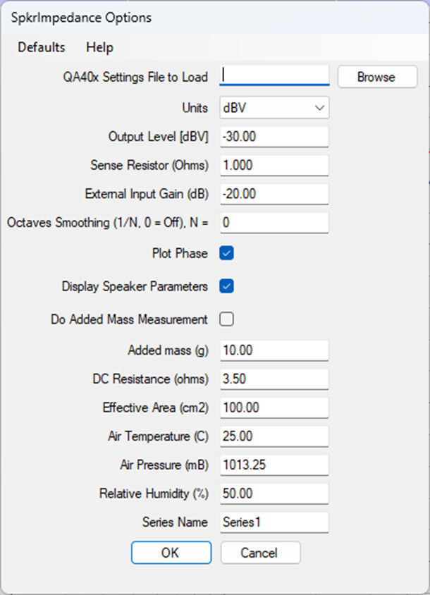
I have been trying out my setup as is in this thread. I am running the automated Speaker impedance test. This works well. In the menu that pops up before the test I check plot phase and calculate speaker parameters. I never see the speaker parameters. I have everything plugged in the same as in Dan’s pic.
Am I missing a step someplace?


Am I posting this in the proper place Matt?
Mark
It’s a good question, I wondered the same!
Reading the documentation here Speaker Impedance Testing · QuantAsylum/QA40x Wiki · GitHub this is intended to print a note at the bottom of the graph with useful parameters.
I bought the 403 and 461 primarily because I design drivers and systems. And occasionally require the other ultra low noise capabilities when I need to test amplifiers. It’s almost all there.
So another question has come up. You cannot do Driver Parameters without either a known sealed enclosure test to shift the impedance or a mass added test to shift the impedance. Anyone have a pre-canned solution for this?
Just import the 2 impedance files (free air+added mass or sealed box) in Speaker Workshop or similar programs, and let them calculate the TS parameters. Watchout the measuring voltage, TS are intended for small signals.
1 Like
Hi @Kravchenko_Audio, yes, this is the correct place! I see your issue. It looks like that the notations that should appear on the lower left and right aren’t showing. This will get fixed quickly. Thanks for noting.
How about the options for entering diameter, added mass or closed box volume in order to do the entire T/S parameter set?
1 Like
I agree you can do this Claudio. I can do this with the equipment that I currently have without needing to plug the data into anything else. I am looking for a one stop testing setup that I can use on Windoz 10. My existing Smith &Larson Speakertester Pro is great. But windoz 7 only. Limited to 20k, but the resolution and repeatability are awesome. I have been designing loudspeaker drivers since 1997. So I have tested a few. But you are totally correct. Low power input or the parameters are off.
Mark
Mark, great measuring tool the “Speakertest pro”. Too bad they are out of business.
I checked your HP, you have made some interesting speakers! Congratulations.
1 Like
Hi @Kravchenko_Audio, can you educate me a bit on your work flow? How would you prefer to test a speaker? Do you run impedance sweep, change mass or box volume, and run it again? And then from that the parameters are derived?
1 Like
Yes. You run a sweep. Establish the baseline impedance and phase. Zero phase crossing crossing frequency will be automatically detected. From this you can do the electrically derived T/S loudspeaker parameters. Then you need to know the following. Active diaphragm diameter. Usually centre of surround to centre of surround. You need to either add a mass generally 25% of known or suspected Mms And you again do a sweep. Alternatively on a driver like a tweeter you use a known volume of air that the driver is sealed against and the test is done. This sealed volume test is also useful for woofers. From the change in the Zero phase crossing frequency you can derive the rest of the mechanical parameters to calculate the Mms of the driver, the suspension resistance and the equivalent volume of air that matches this. Sadly I am not a person very proficient in mathematics. I can point you to a few places that will aid in the derivations. And I know that Claudio is much better at this than I am. If I can help any more I am available generally within a short time.
Mark
Thanks Claudio
I have been in this business since 1989. Started as a box stuffer and kept on learning more. I learn a little every day. The more I find out, the more I don’t know ![]()
Hi @Kravchenko_Audio, I think later this week or early next we’ll do a release with some changes to the speaker impedance plug-in as shown below. This will allow you to run once, add a specified mass, and then run again. You’ll get plot of the impedance/phase for both runs so you can see the shift, and you’ll also get an output with the full T/S parameters. I’m hoping you and others would be able to help validate against other software you are using, and against your extensive speaker library.
Thanks!
3 Likes
I’d be happy to be a guinea pig. My Smith & Larson is a solid piece of test equipment. Very repeatable. So yes, I have tweeters, woofers, planars both flat and AMT style. Those are hard to test as there is a negligible bump in the impedance.
I have been having pretty good luck with the regular speaker Z plug in and don’t know anything about the added mass measurement, so am glad it is an option. Is this the mass of a single driver or the combined mass of the drivers? My purpose is with the measurement is just to see how “honest” a speaker is to it’s stated impedance after many years (for my channel). After your help early on, I use a small integrated amp (Aiyima A07) and these settings:
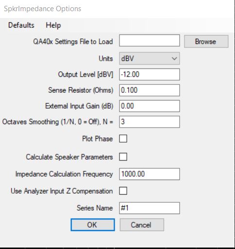
I think it was mentioned that the Calculate Speaker Parameters was not working…? I have been setting the External input gain to 0, though there is gain from the amp which I would consider to be on the output- is that correct. I have had some measurements that compare pretty good to the manufacturer’s data which was taken 30-40yrs ago, so I think the setup works well. I have specific set of cables that I use which makes it easy to connect- one day I hope post some photos of it to forum.
1 Like
Var, the added mass (or closed box) impedance is used to calculate the Vas of a driver. The Vas is one of Thiele&Small parameters, when measuring a driver in free air. The Vas is used to calculate the right type (closed box, reflex etc.) and volume of the woofer box. I have never seen the Vas in a speaker specifications datasheet.
1 Like
Thanks for the explanation. I have not had the itch to build my own speakers so am not “intimate” with the Thiele & Small parameters, though have heard about them. Am glad that the plugin will allow for that when the next version is released for those that do. I measured the impedance of two different pairs of speakers this weekend so this is on my mind ![]()
1 Like
New guy here, just got my QA403 and I’m learning to use it. I have a very deep background in pro audio, and I’m wondering why you put the sense resistor in the high side of the speaker line, where it carries the full output voltage of the amplifier as common mode voltage which needs to be rejected? The long-time standard is to put the sense resistor in the low side (grounded conductor) That way there is zero common mode voltage across it, you could even use an unbalanced input to measure it, assuming no ground difference issues. The loudspeaker input is balanced and floating and doesn’t care if it’s grounded or not. It just seems like you’re asking for trouble by giving your CMRR about 40 dB more work than is necessary.
1 Like
Hi Dale,
Welcome! It’s a good place with lots of fun technical stuff going on.
My hunch is that CMRR is not the only source of noise.
In your example you reduce the CMRR requirement, but the ADCs see very different voltage levels, this is a bit like measuring a 1.5V battery with the 200V setting on your DMM. Matt could probably give you a fuller answer, but I think you can trade CMRR noise for quantisation noise. Maybe having the current sense in the high side wins overall because the CMRR is so good?
Matt did a blog post measuring very high power amplifiers in which the current sense was sandwiched between two load resistors: 4/0.1/4 Ohm to give the amp an approx 8 Ohm load. This reduces the common mode because otherwise it would be too large to measure. But it’s along the same lines you mentioned, yet voltages are same magnitude because of the symmetry.