The test fixture boards arrived yesterday. The SMD resistors provide 6dB of attenuation using a voltage divider (thanks @MarkT), there is a zero Ohm resistor in the third position so that can be used as a T-pad also.
Set up
I have the balanced outputs of the QA403 driving the balanced input of the amplifier, the BTL output of the amplifier connects to the test fixture through the “AMP” jack socket and we tap off voltage across the DUT and voltage across a 0.1 Ohm current sense resistor which are sent to the QA403 inputs via the -6dB attenuator and BNC connectors. The DUT (resistive load or inductor) is connected across the output of the “LOAD” socket.
(NB I am using jack sockets because I’m mainly interested in guitar amplifiers and that is the standard).
I used the REST API to drive the measurement because I wanted to apply the external gain of -6dB globally to all inputs and was not sure how to do that with the application software. This script sets the generator to 100Hz and loops over different output amplitudes. At each measurement point it requests the THD percentage, I also grab the spectrum of the left output (voltage across the DUT) and process it a little to get the peak value.
import requests
import numpy as np
import base64
import matplotlib.pyplot as plt
import pandas as pd

results = []
external_gain_dBV = -6.08
amplitudes = np.linspace(-60, 0, 61)

for amplitude in amplitudes:

    # Set analyser output voltage that is driving the amplifier
    requests.put(
        url + f"/Settings/AudioGen/Gen1/On/100/{amplitude}"
    ).json()

    requests.post(
        url + "/Acquisition"
    ).json()

    # Use the application to calculate THD
    thd_data = requests.get(
        url + "/ThdPct/100/1000"
    ).json()

    # Grab the left input to find the level
    data = requests.get(
        url + "/Data/Frequency/Input"
    ).json()

    left = np.frombuffer(base64.b64decode(data["Left"]), np.float64)
    #right = np.frombuffer(base64.b64decode(data["Right"]), np.float64)
    freq = np.arange(left.size) * float(data["Dx"])
    idx_20Hz = np.where(freq > 20)[0].min()
    leftdBV = 20 * np.log10(left[idx_20Hz:])
    leftdBV
    results.append({
        "output": amplitude,
        "input": np.max(leftdBV - external_gain_dBV),
        "thd": float(thd_data["Left"]),
        "external_gain": external_gain_dBV
    }
    )
df = pd.DataFrame(results)
df
THD vs Power
Here is the THD (%) data verse power for the amplifier driving a 15 Ohm resistive load and driving the 25mH inductor at 100Hz, so Z(100Hz) = 16 Ohms.
There is the data as log-log and linear plots,
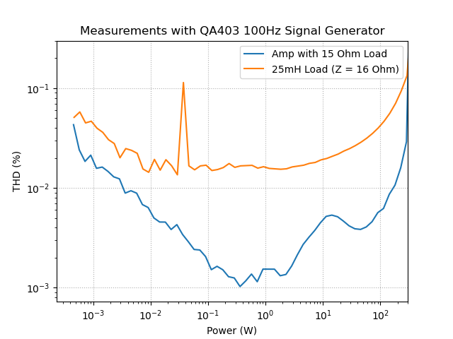

Looking at the log-log plots: there seems to be an outlier in the measurements around 40mW, ignore that. But otherwise you can see that the inductor distortion is 0.1% at 250W. Looking at the linear plots: at higher power the reference and the inductor curves have similar shape so I cannot say that this is saturation in the core or just distortion in the amplifier. I might lean to say that it is core saturation because the gradient is rising faster for the inductor than the amplifier at the same power.
I took a quick look at the waveforms, but visually I found it quite hard to see 0.1% THD and didn’t save the data to look more closely.
Worst Case Thermals
I put the QA403 into IDLE so it was continuously generating a 100Hz tone and left the inductor for 20 mins. it very slowly reached 100C (that’s 212F for my freedom loving cousins) with 300W input at 100Hz. This is an absolute worst case, in practice energy in the signal will be spread over the audio band and will have a much higher crest factor. So I think that is acceptable.
Next
I want to see if I can use the impedance measurement feature of the QA403 to measure the impedance as a function of input power to see if we can see the inductance fall off. This will unambiguously show how much the core is saturating.


