I’m not an engineer - just a vintage audio hobbyist. I am putting together the equipment to align the tuners in vintage receivers. I have an FM stereo signal generator and oscilloscope as well as a QA401 I have been using to measure amplifier distortion. The alignment procedure calls for injecting the FM signal at the antenna input, and then connecting a scope and distortion analyzer to the Tape Output. At several points in the process, you adjust a coil to get minimum distortion. I’m used to measuring distortion relative to the output of the QA401. I would not be using the output in this case. So, can I use the QA401 for this measurement? If so, what would be the setup? Thanks!
1 Like
Hi @srtate1, yes should work fine. On the QA401, I’d go with a smaller FFT (8K or 16k, to give you a better update rate). If amplitude accuracy is of paramount important, then use FlatTop window. That will let you see harmonics down to around -100 dBC. Otherwise, use Hann. Just understand that with Hann your amplitude error might be 0.5 dB or so. Probably not important for this task. But Hann will give you a better skirt shape. And of course, look at the distortion with atten on and off. The better reading will be the true distortion level. For example, in loopback with 0 dBV in, the measured distortion in the +6dBV range is around -100, and in the +26 dBV range is -110. And thus, the -110 is the more accurate figure. But my guess is that with FM your distortion products will be much much larger.
Feel free to share plots as I think it’d be interesting to see.
1 Like
Thank you, Matt. This is very helpful. I will give this a try and see what I get.
Hi @srtate1,
As it happens I did this very test yesterday! Connected the QA401 to the tape output of 1970s Hitachi SR-303 receiver whilst injecting a 98MHz / 600Hz FM signal. Adjusted the discriminator until %THD was at it’s lowest. After getting a silly number to start with, I realised the QA401 THD setup had to be configured to use 600Hz as the reference. I used a small FFT to get the fast update whilst adjusting, then increased it once I though it was peaked to to check it was a real measurement. I didn’t play with the windowing as proposed by @matt.
The Hitachi service manual, which incidentally is excellent, sets up the discriminator initially as step 2 of 9 using the usual sweep generator / scope / wobulator. The distortion test is a fine tune at step 6.
Sorry I hadn’t read this before doing the test otherwise I’d have captured a screenshot.

This post is making me think - as my signal generator allows for external modulation, I could connect that to the QA401 output and do a frequency response test! Watch this space.
SABristol, that is exactly what I am wanting to do. Can you tell me where you set up the QA401 to use 600 Hz as a reference?
You can set that in the THD options context menu. Do CTLR-click on the THD button (or click and hold) and the window will open:

There, you pick the fundamental selection. Normally, it will be at “highest peak” and so if you input a 600 Hz tone that is “stronger” than every other part of the spectrum, then it will be used as the reference. And your 2H will be 1200, your 3H will be 1800, etc.
And you can verify it by by looking for the green “F” underneath the peak. That “F” shows you what the analyzer is using as the fundamental.
Good luck, and do post a plot if you can!

1 Like
Some cautions and details on measuring FM tuners, from painful experience.
First, read the info from Sound Technology on FM tuner alignment before you go too far: http://www.mcmlv.org/Archive/TestEquipment/Sound%20Technology%201000A%20FM%20Stereo%20Generator%20Manual.pdf
There is other good stuff out there: Updating the Sound Technology 1000A
And of course the FM tuner nuts: Tuner Information Center - Vintage Stereo Tuners
Distortion- many FM generators are not that low in residual distortion. Some Japanese generators and an ST1000a that has been very carefully tweaked can get down below .01%. But the effort is really involved. Modulation level is important. if your modulation is too high the distortion will go up a lot but not relevant to proper modulation. Calibrating modulation levels is also really involved. I had to align my ST1000a before I could properly calibrate a Kenwood tuner to check the car fm xmtrs I was qualifying… The process is pretty involved but adequately documented in various places.
Frequency response; the generator may not have the appropriate pre-emphasis and this become a double edged sword since if it does a flat signal will overmodulate above 2 KHz. US tuners are 75 uS and EU (and other parts of the world ) are 50 uS. Most of the little car FM modulators are also 50 uS. And then the 19 KHz pilot filter is a hard bandstop at the top of the band. Maybe Matt can create a test sweep with the 75 uS pre-emphasis incorporated to get a flat response from the tuner? And stop the sweep before it triggers the pilot detector.
Stereo alignment is a different can of worms.
1 Like
Thanks for the info. I know I’m treading into some muddy waters with tuner alignment, and I may decide it’s not worth it. I do have a Sencore SG80 generator that has been calibrated, and appears to be up to the task distortion-wise as I browse the forums. But my plan is to follow the steps in the Marantz service manual, which appears to outline fewer steps than I see in a complete alignment with other receivers. I will be learning as I go, but I have done a lot of research to try to understand what is going on. I’m going to tread lightly, and first see if I can get baseline test data that makes sense and move forward from there. I restore a lot of Marantz receivers, and most really don’t need an alignment. But occasionally, everything appears to be working, but the tuner just won’t latch on to anything but the strongest signal. So, I’m going to grab one of those and see if I can improve the alignment following the service manual. Thanks for the links. I will be studying them.
Thanks, Matt. That is what I needed. I’ll let you know how I fare.
From a very wet and windy Blighty, I did a very quick rough and ready re-test of the audio spectrum of the tape output from a Hitachi receiver, with a 98MHz / 600Hz tone / 60kHz FM deviation / 2mV injected from a Siglent SDG2122x arb sig gen (I don’t have a proper FM RF gen). Although a THD of 0.27% isn’t great it is significantly improved by reducing the deviation. I think I was only using a 12kHz deviation when I actually did the alignment and the THD was nearer 0.1% then. The alignment was about peaking the receiver rather than the absolute value anyway.

I suspect @1audio will cringe…but as a lone hobbyist fumbling around in the dark I don’t mind feedback on the above 
Simon.
This is great info. My SG80 signal generator is new to me, and I have been missing some cables. Just got them in the mail yesterday, so plan on hooking things up to see what kind of test results I get. As you said, the actual goal in alignment when using the Distortion Analyzer is to simply adjust to minimum distortion. So absolute values are not that important. Your setup parameters will be helpful in getting to an initial setup. Thanks, again!
1 Like
@srtate1 I was considering buying a traditional FM Stereo signal generator but recently spotted this on YouTube channels “Electronics Old and New by M Caldeira”: Perfekter Signallieferant - HQ-Stereo-UKW-Prüfgenerator SUP3 | ELV Elektronik | ELV Elektronik Online Shop | Kompetent in Elektronik. I’ve written to them to try and get one as they don’t seem to deliver to UK. They’ve not replied so far.
I have run into one of life’s little snags. I bought this SG80 about 6 months ago from a trusted tech. I plugged it in and it powered up at the time. I went to turn it on today, and found that the fuse cover, with fuse, is missing from the back of the unit. It is a square “Press Here” type of cover, so probably got pressed during one of my workshop reorganizations. I have searched all over my workshop and can’t find it. So, I think I have found the same fuse holder at Mouser.com and have ordered one. I will get it in two days and be holding my breath that it works. Grrrrrr.
1 Like
I managed to get my new fuse cover and get the SG80 working. I really had trouble figuring out exactly what the test protocol was for this Marantz 2270. But I reached out to a friend who does this regularly, and he really gave me good instruction on the alignment in general. I used the internal audio generator of the SG80 with a 400 Hz tone and a 1kHz tone, just to see the difference. My friend had me go through the initial steps of getting the local oscillator and front end peaked up. The last step is adjusting the discriminator to get minimum THD in the audio signal. I’m not real confident in the absolute number I received of 0.5%, because the unit performed so well after alignment. The signal was very clean looking and strong on the oscilloscope. It could be my signal generator or something in my setup. But the main thing I wanted was the ability to see the THD figure move in real time with my adjustments. It did indeed do that. When I started the discriminator adjustment, THD read around 1.0%. After adjustment, it was about 0.5%. As a quick and dirty method of gauging whether my alignment procedure helped or hurt my reception, I engaged muting, which lets the tuner pick up only the stronger stations, and counted how many stations it would latch onto before aligning. I was able to grab 23 stations at that point. After the complete alignment, the same receiver picked up 34 stations with muting on, and the background was much quieter on our single classical music station. I would call my first efforts a success at getting the test equipment setup for a good FM tuner alignment. Now, I need to experiment with my setup and my test settings to see if I can lower that THD value. Any ideas? Here is the one plot I did after making my discriminator adjustment. I’m not real sure what it tells me, but my primary interest was in being able to find the minimum distortion point in real time as I made my adjustment. I believe I was able to do that.

1 Like
Hi Steve,
Good work. With the extra channels it does sound like you have got the RF and IF stages better aligned 
My observation comparing our plots is that the noise floor on mine gradually increases between 1k to 12k whereas yours does the opposite. This may be pre-emphasis / de-emphasis at work here.
Really makes me want to sort out using the QA-401 to do a Bode plot. As @1audio mentioned, I’ll need to add pre-emphasis for it to work. Not looked to see if there’s a UK spec weighting filter already available in the QA folder. If not I’ll have a go at creating one myself (even though a simple single pole, undoubtedly need @matt’s oversight). See User-weighting-and-riaa Post
This is what it looks like without emphasis correction:

Couple of other points:
- In my rush to do the retest I’ve remembered that I didn’t put a terminator on the unused input so that may contribute to some of the noise (since checked and the difference is negligible).
- Whereas you did stereo, I can’t generate a FM stereo signal so I only used one channel (hopefully I’ll be able to get one of those ELV SUP3 I mentioned earlier).
- The only reason I used 600Hz tone was because it’s a bit easier on the ear when aligning.
I must mug up more on the links that @1audio posted.
Anyway, to answer your original question - yes it seems we can use the QA-401 to measure FM distortion 
Simon.
And hopefully with the new QA-402. I’ve got to align a few NAD 4300 tuners. I’ve got a RE SMG40 stereo generator I’d like test as well. Looking forward to the QA-402 when it’s available.
1 Like
I created the user weighting file for region 1 with the following content:
#FM de-emphasis for Region 1 (Europe and Asia)
#fc = 3.1831 kHz
#See www.radiomuseum.org/forum/fm_pre_emphasis_and_de_emphasis.html
#Simon BAYNES 24-Jan-2021
20, -0.03
30, -0.04
40, -0.05
50, -0.07
60, -0.08
70, -0.09
80, -0.11
90, -0.12
100, -0.13
200, -0.26
300, -0.39
400, -0.51
500, -0.63
600, -0.75
700, -0.86
800, -0.97
900, -1.08
1000, -1.19
2000, -2.12
3000, -2.88
3183, -3.01
4000, -3.53
5000, -4.10
6000, -4.60
7000, -5.05
8000, -5.46
9000, -5.83
10000, -6.17
20000, -8.62
@matt is it correct?
This gave the following Bode plot for my Hitachi SR-303L receiver:

The Hitachi service manual specifies for the FM stage:
Response as 30-12kHz +0.2 / -1.5dB.
Distortion as 0.15% at 100Hz and 1kHz
Seems I’m a little out on the FR but within spec for distortion. Compensating for emphasis should be done on the output of the QA-401 rather than the input to avoid over modulation so what I’ve done isn’t quite right and it makes more sense to put a pre-emphasis RC network between the output of the QA-401 and the modulation input of the FM sig gen.
1 Like
Yes and no on the reemphasis. FM has a specific limit on modulation so if you sweep with preemphasis on you will overmodulate or run at a reduced level. You can add back boost on the output, but probably best done with a correction curve, something that the QA401 supports. I would need Matt to show how in this application. Also the distortion is sensitive to the IF bandwidth. Meaning that low distortion wide bandwidth need strong local stations.
1 Like
Following on from earlier posts,I eventually got around to building a FM Stereo Test Unit based on a Pira CZ Stereo Encoder bought through eBay and an active switchable pre-emphasis filter. This is it in a not quite completed state:

The FM Stereo Test Unit is connected up to the DUT through a Siglent SD-2122x AWG, and the QA401 connected as so:

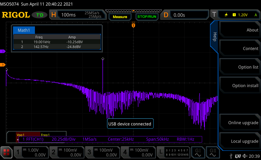
The MPX output spectrum looks like this whilst the QA401 is doing a FR chirp. You can see the L+R (mono), the 19kHz pilot, the lower L-R spectrum, the 38kHz suppressed carrier and part of the upper L-R spectrum. A couple of observations here are that the L+R (mono) level at -24dBV is too low, as for 100% deviation the Siglent AWG needs 12dBV and the pilot should be -20dB below that.
Here is the resulting frequency response of the DUT, a Luxman T-88v:

And it’s spectrum:

Distortion needs to be taken with a pinch of salt as until I’ve got al the levels right, it isn’t necessarily true.
This is early days and my immediate thoughts are the tuner doesn’t actually roll off so early at the top end ands suspect I need to take a look at the filtering in the FM Stereo Test Unit. I’ve got another tuner on the bench so can compare that.
Anyway, subject to some tweaks in filtering and setting up the myriad of levels correctly, generally the concept works so I’m happy with that
1 Like
Nice, lots of work, looks good
1 Like