Hi @SigurdR, what type of analysis are you needing to do on the noise? Wouldn’t AC coupling introduce a phase shift that you must then contend with? Why not just export the time-domain data and do whatever analysis you need on that? Or acquire the data in real-time via matlab and analyze it that way?
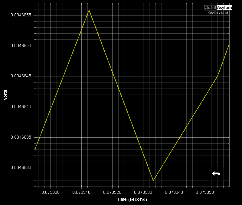
Also, if you stop the acquisition you cna use the mouse middle button to pan around and use the left button to draw a zoom box around what you want to see.
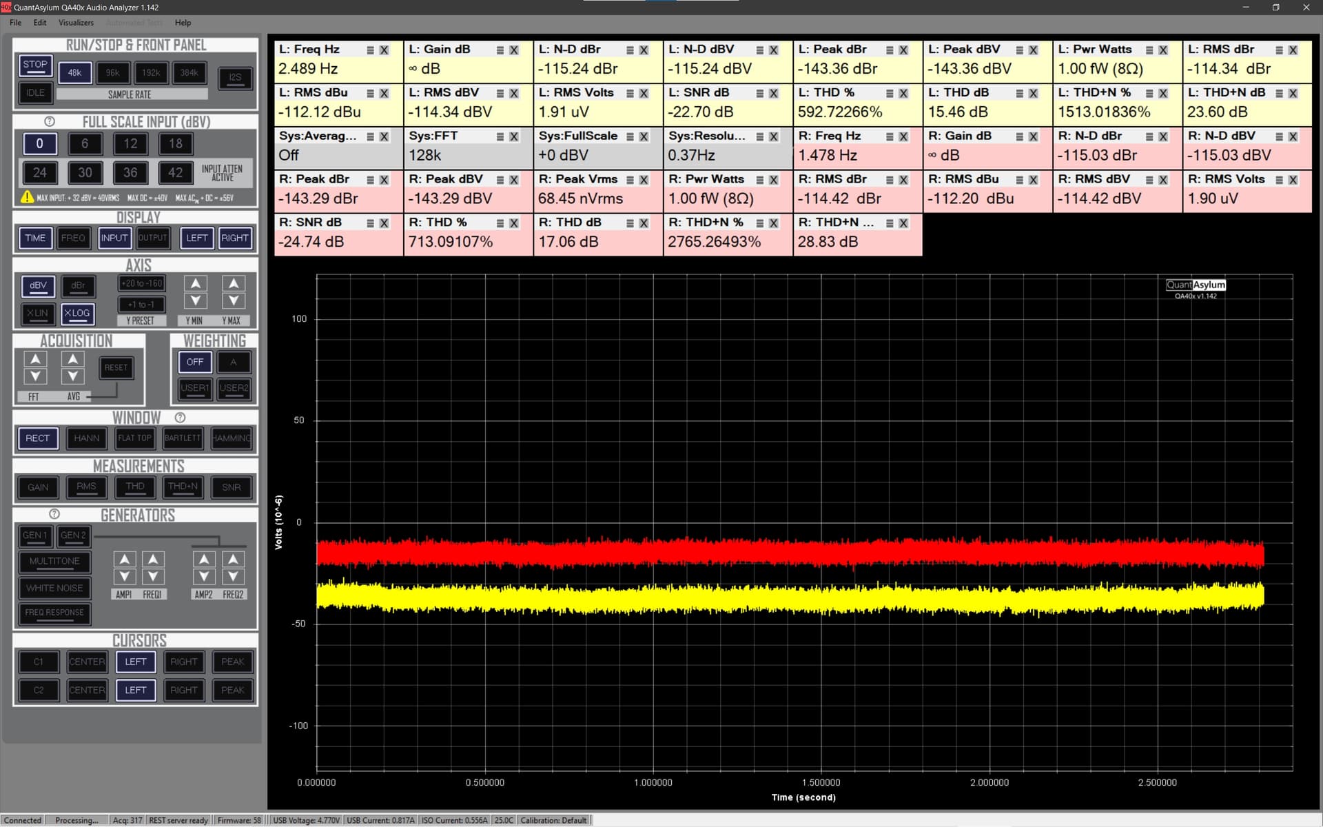
I want to measure the noise to see how the noise level is in the time domain. Then I can estimate noise RMS. Yes, I see that the software also measures RMS but I am old school and want to see the noise on the “oscilloscope”.
I did not know about the panning or moving the screen around. Thx for the tips! I am now able to do what I want.