In the current version of the software for the QA403/QA404, what is the max sample rate that can be used for external DAC testing? Most of the DACs that I’d like to test are 24-bit and go up to 384 kHz.
Hi @bryman79, 192Ksps is the max supported by the software and hardware. However, there is a 384Ksps “experimental” mode in the software (enabled by the -384k command line option) where the ADC should run at 384Ksps.I’d not consider the -384k mode super reliable, but for a quick check it can do fine.
Here’s a Topping E70 Velvet forced into 32-bit 384Ksps in Windows, with the QA40x app launched using the -384k command line option. That enables the 384K sample rate button to be pressed. Note that the analyzer DAC is delivering random junk in this setting, so don’t have anything connected to the DAC outputs. And here’s the plot out to 200kHz shown below. You need a notch to unlock the measurement down to -125 dB THD+N or so. As you can see from the plot, mirror mode is working at 384K, along with acquisitions.

And here’s the same plot with the analyzer inputs shorted so you can see the residual noise of the analyzer.
Comparing these two, we can see the Topping E70 Velvet appears to have a bit of hash up around 150 kHz that isn’t there when the analyzer inputs are shorted.
1 Like
How about sample rates from the other sample rate family? Such as 44.1 kHz and 352.8 kHz?
Thanks,
Bryan
Hi @bryman79, the only sample rates supported are 48, 96, 192 and (experimentally) the 384.
While a lot of DACs and ADCs can support both via a PLL, the frequencies generally require a dedicated crystal to get the most out of the part. So, you either pick 44.1 and multiples thereof, or 48 and multiples thereof.
While I am searching for a way to use 384 ksps DAC reproduction, I made the decision this morning to try and remove the digital isolator (I2S) from the QA403 I have here. Connected the signal lanes as well as the GND’s together, but keeping the supply voltages of digital and analog separated.
Everything up and including 192 kHz sampling is still working. I only need to worry about GND loops (which is not a difficult problem yet with my devices).
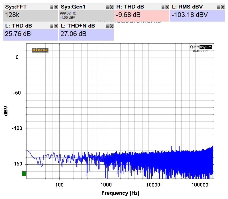
The DAC / ADC is not always performing well in this way, but with some waiting I found a way to get usable results when analysing a steady generator with low noise floor on 384 kHz sampling rate. (Gen 1 @ 0 dBV, THD -110 dB, Sample rate 384 kHz).
After switching to 384 kHz I need to let the system stabilize for about 5 minutes; and in this time I can see all kind of spikes walking through the spectrum, until it looks like jitter and then starts to narrow down. First In the first time I see a lot of harmonics: skipping bits somewhere? Later when it starts narrowing down it looks like a PLL which is really slowly locking. On my scope I notice that MCLK has a swing of from 600mV to 2.6 V only, never reaching its supply lines.
So to be clear:
- It is not working great (yet). Running a AmpFrequencyResponseChirp is not OK, gives a mess in the responses.
- I did need to modify hardware on the board, probably ruïning my warranty
I really hope @matt would like to support this, if not I will accept that also; I understand how running a small bussiness goes.
Maybe he can point me in a direction that could solve the issues; I would be glad to do a part of engineering to get it working. I expect signal integrity, PLL / clock recovery settings / filter settings could be a problem.
Next steps would be either sniffing the I2C bus, buffering the clock signals, checking and improving signal integrity, cheking if its the DAC oor ADC.
Then also some software limitations should be worked-around: eg THD calculation seems strange comparing the numbers with the spectrum; The generator does not function well around/above 100 kHz.
Included are some graphs for the interested:


Hi @Elmar, is the difference between the first and second plot just that you waited a bit?
Yes. Thats the only difference!
However I tried on 3 different systems (with SW release 1.199), and some stabilise faster than others.
Using the generators above 96 kHz will cause spectral reflections going both sides (+ and - 96kHz); but below 96kHz that also works. I validated the measured spectra with a PicoScope 4262 and the spectra look the same, so it must be on the generator side. Which makes sense because I gues the ADC is the MCLK generating device.
This could also be the reason that a frequency response measurement turns out awfull.
Hi @Elmar, yes, understood about the difference. You are correct about the ADC being the I2S master. The ADC and DAC obviously are on the isolated side. The processor is on the USB side. The digital isolators impose a ~10nS delay in both directions. For receiving, the processor doesn’t care because all signals (MCLK, LRCLK, data) are delayed. But the processor must then drive the DAC. And so the DAC data signal effectively sees a 10 + 10 nS delay. This is not a problem at rates up to 192K. But beyond that, the combined 20 nS of delay is a problem. At 384K, the bit clock is 12.28M=81nS.
Now, removing the isolators should eliminate the 20 nS. But consideration needs to be giving to setup and hold times. You can probe the I2S signals on the isolator pins. I think they are marked. But the upshot is the DAC timing margin is too tight at 384k. It might be fixable in firmware tuning someday. But for now, it must remain experimental.
PS. You can see the signals on the isolator pins. From the top it’s DAC data, ADC data, BC=Bit Clock, LR Clock. The OVL and OVR are overload indications for right and left input channels. This of course flows from the iso side to the USB side.

1 Like