Until you redraw the schematic to actually show a centre-off switch, people will continue to be confused.
Your schematic doesn’t link the two sets of poles as double throw and neither does it show a centre-off position.So no, your schematic is NOT correct. Easy to fix, just put a dotted line between the two sets of actuators (1a and 1b) and put the moving contact in central position (0) in between the two contacts (I and II).
I want you to understand that this is not a finished schematic, but merely a semantic representation of the idea of how one can easily build a 0 dB, 6 dB, and 10 dB attenuator using minimal standard components. I have never claimed anything else.
This schematic is taken from a simulation; unfortunately, the MicroCap 12 simulation software I used does not include a ready-made switch macro with on-off-on functionality! Had I drawn this using two on-on switches connected in series, people would have been even more confused. I have clearly indicated the type of switch (3 position dual-throw) using big letters in the schematic itself. This is also explained in the functional description, as well as in the discussion that took place. I apologise if some beginners in electronics have not understood the nature of the switch. I did not set out to redraw this as a separate schematic using an ECAD tool or to design a PCB; it was never intended to be a finished project or transferred to a PCB, but rather to share this basic idea with forum users to encourage home-brew attenuator builds. I invite you to redraw it if you see it necessary.
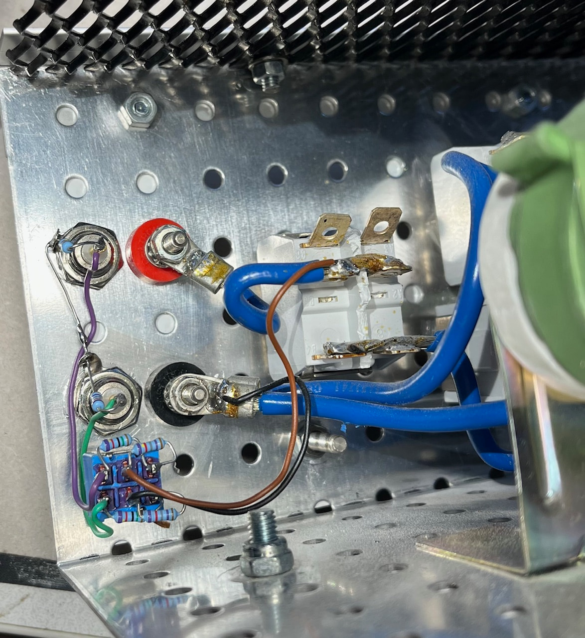
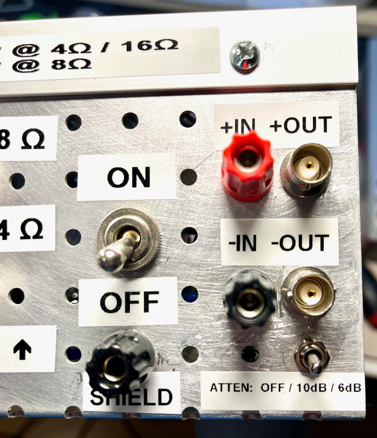
I have included below pictures of my implementation that supports 1 channel balanced measurements - be it from a normal or bridged amplifier. The attenuator is built into my home-brew 300W/600W dummy load with selectable load resistances (0Ω/4Ω/8Ω/16 Ω). The two banana sockets are for the wires coming from the amplifier output under test, and the two BNCs connecorts connects naturally to the QA403 inputs.
The 3-position dual throw ON-OFF-ON switch can be used as the solder lugs for the few serial resistors required. The shunt resistors are soldered in parallel witch each BNC.
The front panel where the 3-position ON-OFF-ON DPDT switch is located, with its markings. Off means no (0dB) attenuation.
Cheers - Christian