Complete Amp running in Class A:

Am a bit confused as to why you are not showing both channels info at once. I have been using HANN filtering for most of the measurements- sometimes RECT but never FLAT TOP, and prefer dBr for the display for the majority of what I measure. Not a fan of how you are connecting your load to the speakers, but none of this will improve what is being measured. Too bad you were not close to me.Did you try to measure another piece of gear?
Am a bit confused as to why you are not showing both channels info at once. Every post has shown both channels, except 41 & 42 which was only shown the for the purpose of showing that I had conducted a full amp test.
I have been using HANN filtering for most of the measurements- sometimes RECT but never FLAT TOP, and prefer dBr for the display for the majority of what I measure.
Every post has shown HANN, except 41 & 42 which was only shown the for the purpose of showing that I had conducted a full amp test.
Not a fan of how you are connecting your load to the speakers, but none of this will improve what is being measured.
I do need to upgrade my Cable Set.
Too bad you were not close to me. Where are you located?
Did you try to measure another piece of gear? YES
Have you ever tested a Yamaha CA Series Int Amp?


Your load connection makes more sense in the latest photos. Never have tested a CA series amp but have done one or two that ran in either A or AB- possibly a Yamaha amp if I remember correctly. I think somewhere I posted a link to my loads- they have been improved since then but basically the same- if I find the link I will post it. I live in Tucson. I do not see the numbering for your plots. Did your other piece of gear- hopefully a preamp- look OK?
Yes it tested as expected
The post 45 was in response to the requested post by restorer-john, any thoughts on the results?
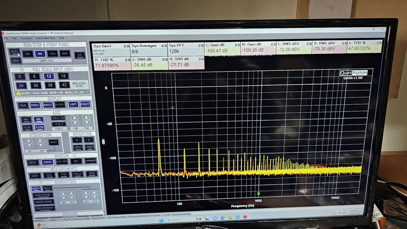
The plot on post 46 shows a bad 60hz hum which I would find liveable coming out of the amp or amp preamp combo, but not out of the preamp by itself. Did you look at the +/- 50 power supply with a scope, or you can us the qa403 with a scope probe set for x10? You may want to isolate the ground terminal with one of those a/c adapters that go from 2-3 pins- just to see if it makes a difference. Here is the link to my load video- I have re-done the wiring to 12 gauge wire everywhere and replaced the banana jacks except the 2-way ones.
Did I configure the test correctly?
I would note CA has rewired the amplifier with a three pin IEC. Whether he has chassis earthed it or not and where that is tied is anyone’s guess. The US CA-1000 and the later CA-1000mk2 were unearthed two wire cables, with the CA1000mk2 having the double insulated symbol. That said, in countries like Australia and the UK, they were chassis earthed, many hum related issues stemmed from the fact the CA-xxxx series had only a few key parts of the circuitry tied to the actual chassis panels and were not designed with the express implication of a safety earth.
Eddy currents can form and they can be very difficult to chase down. An ‘earth’ and the neutral should be at the same ground potential, but in reality in a normal domestic power distribution, they are never at the same potential. Depending on leakages/coupling from the power transformer to the chassis, more currents can flow. As it is single ended measuring he’s doing, and the QA-403 is isolated from actual earth/ground- the potential for mains noise is large.
The spectrum to me, looks like a potentially floating chassis from mains earth, with respect to the QA-403, one that has induced mains in the OV return (spkr ‘-’).
Here is the difference with an old benchtop oscillator where the outer BNC (0V/gnd) is floating with respect to mains earth and then attached to a neighbouring instrument’s earth screw. The difference is significant.
Experiment with your earth/0V/returns and inspect every point on the CA-1000 chassis where the circuitry is ‘grounded’. That includes the 50+ year old capacitors tieing the RCA outer shells to the chassis etc.
Floating:

Mains earthed:

1 Like
The ground in the IEC is not connected
I am aware of exactly what you are speaking about with the grounds in this amp. Extreme care has been taken to document the original Yamaha ground paths and has been returned to those points. Most all grounds are at a single point location on the Electrolytic Board:

Extreme care was also given when changing out the RCA connectors on the rear panel to insure they are isolated from the panel and each other. A chain of connections was made per the schematic:

The 0.01uf capacitors were replaced with Panasonic ECQ’s. Resistors were replaced with Vishay Carbon Film 1%.
1 Like
This is of great interest to me to understand. The Rear Panel RCA grounds are terminated to the chassis and do not return directly via hardwire to the Electrolytic Board single point ground. Should I pull it from the chassis connection and run to the Electrolytic Board Ground Point?
Side note FYI: All components of the MIC have been removed and the +50vdc has been removed at FR402

I moved the unit into my sound check environment and I do hear a slight hum above 50% volume.
The spectrum to me, looks like a potentially floating chassis from mains earth, with respect to the QA-403, one that has induced mains in the OV return (spkr ‘-’). I had to think on this over the day, I now see what you are saying. I assume nothing can be done about that, can’t lift the BNC ground from the QA403.
Here is the difference with an old benchtop oscillator where the outer BNC (0V/gnd) is floating with respect to mains earth and then attached to a neighbouring instrument’s earth screw. The difference is significant. Are you thinking I should make that IEC Ground connection to the Electrolytic Board single point ground?
Just one thing I wanted to check, are you running the amp through a DBT?
That can limit the current and cause ripple in the transistor based PSU section NA-06332.
No Sir, I did start the unit under DBT but not while conducting this test.


Yep. The one not using Filter Capacitors is the one that needs proper current supply to be able to deliver smooth DC.
I assume they are used for different sections of the amp?
Looks like you did work on the PSU board already but maybe you didn’t swap zeners and diodes?
I assume that one feeds the pre-amp stages?
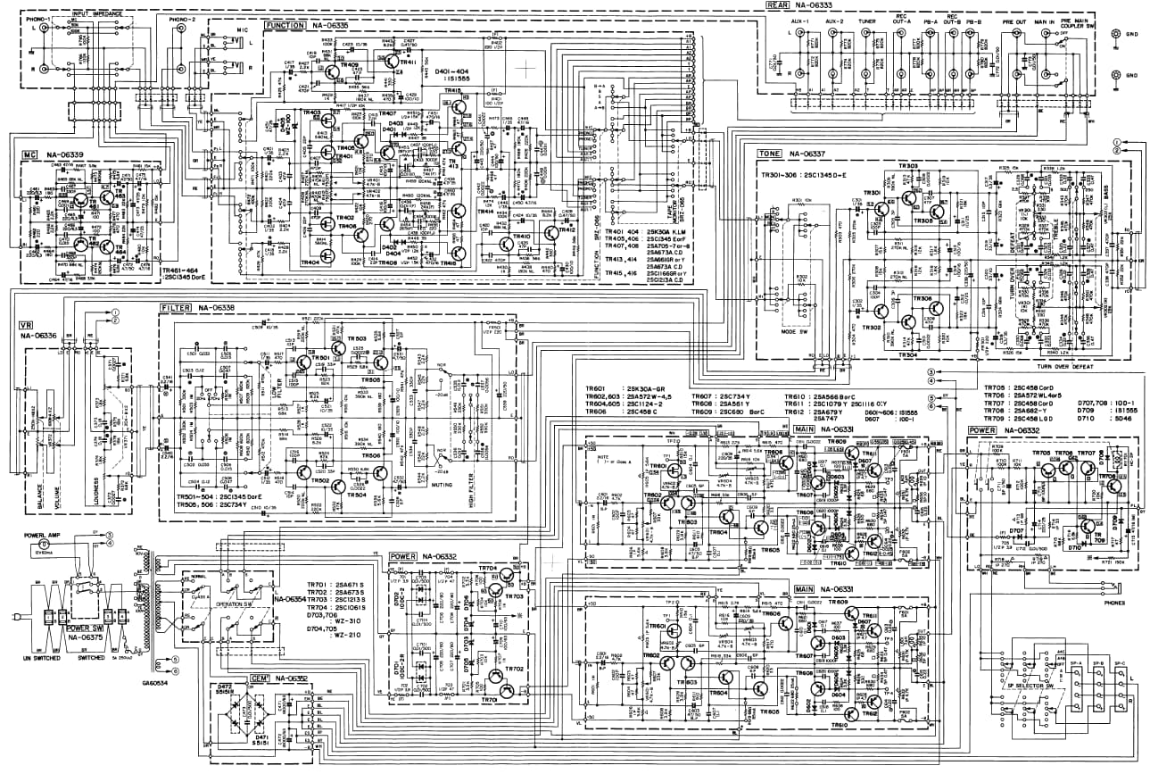
Yes looks like the NA-06352 PSU is only used for the main Power Amp.
The rest is powered via NA-06332.
Look at and maybe replace TR701-TR704 and (zener) D703- D706.
