Hi @kawal, the input impedance is 100k, and that is formed via a 93k in series with a 6k resistor. Imagine a pair of resistors in series with ~93k on top and ~6k on the bottom. When the attenuator is off, the input buffer taps across the 93k+6k ohm, and the input impedance is whatever you select at the terminal.
When the input attenuator is active, the input buffer selects the top of the 6k, giving an attenuation factor of ~6/100 = 0.06 = -24 dB. But now, no matter what input impedance you have, the input to the buffer is 6 || 93 best case. That means the input BJT current noise matters more, but it also means that you have a ~6k impedance that can pick up stray fields even if you short the inputs. As you know, power line is very difficult to shield usually requiring mu-metal and custom connectors. That isn’t likely to happen at a $600 price point.
Grounding the unit helps but that should not be the normal behavior.
If your setup doesn’t already had a ground established, then you’d not expect to see it improve further with another ground connected to the QA403. If it does improve, then it seems more likely that the system ground established isn’t correct for whatever reason.
Take a look at the measurements at the link below. You’ll see commercial class D (Behringer) which are kind of sloppy, and super refined class D (Hypex). There’s a discussion on working to get power line out of the measurements given the XLR inputs. Remember, the -105 dBV you can see for your 50 Hz is about 5uV of power line that is seeping into the measurement.
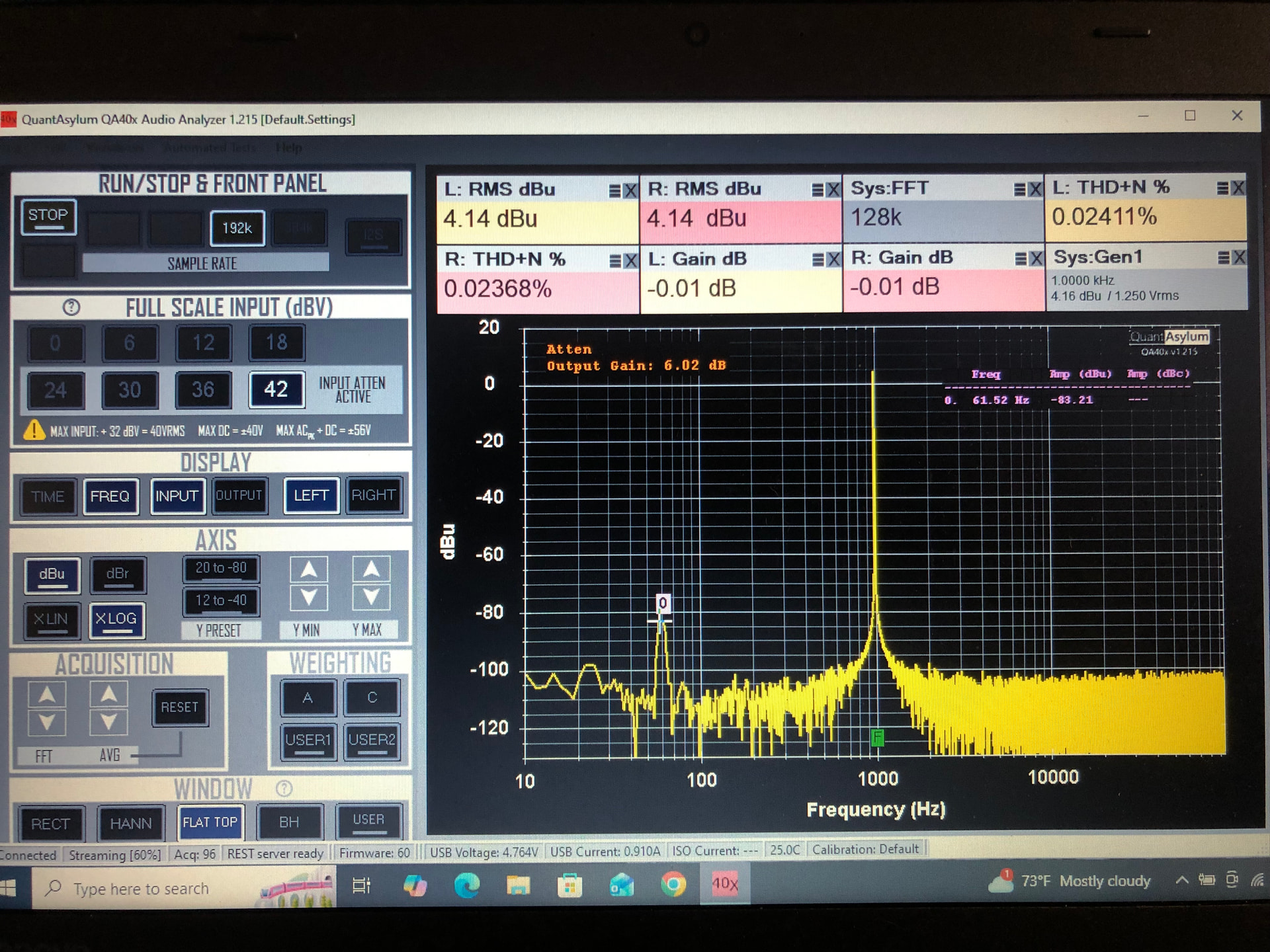
You can convince yourself the coupling is radiated by examining the power line component witt the equipment in different orientations. For example, here’s the QA403 sitting next to the Hypex vertically (none of the QA403 feet touching the surface of the desk)
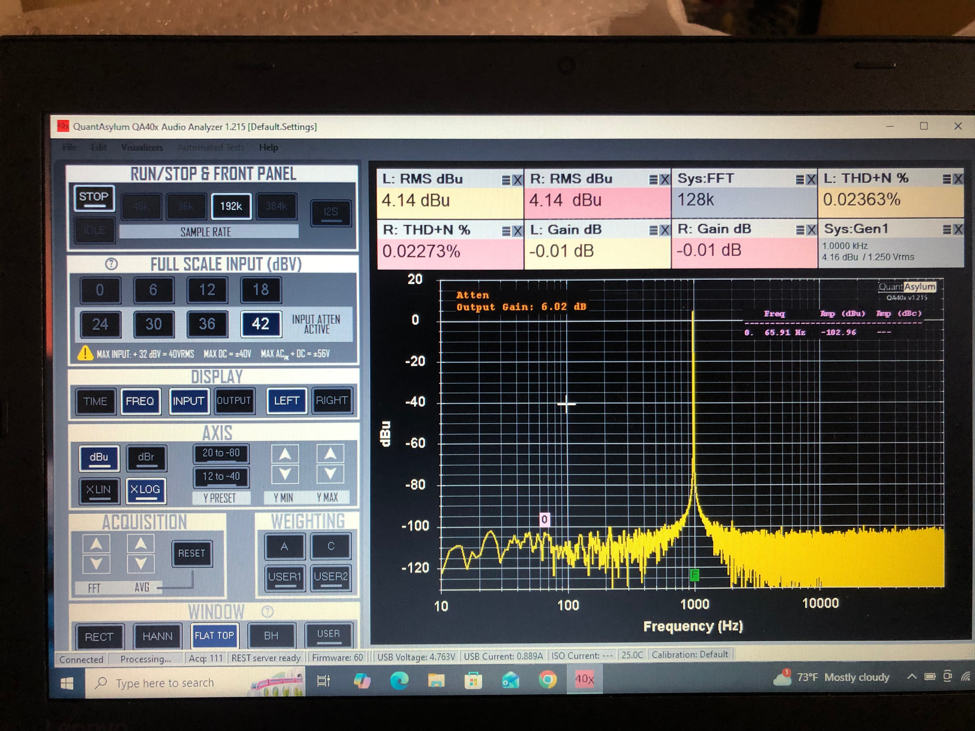
And here it is sitting next to the Hypex with all four feet of the QA403 touching the surface of the desk:
Big difference! But all I’m doing is changing the amount of E and H fields (mostly H fields) coupling into the QA403 by changing the location. And since it’s probably H fields, that means it comes from power line currents and will thus get stronger as amplifier power outputs increase.
And scooting it around a bit more can make the 60 Hz vanish leaving us with 2H around -111 dB
Also note that Class D amps (like I’m showing above) can have power supplies that are very nasty for power line radiated emissions. Finally, @VAR posts a lot of amplifier measurements at his youtube channel HERE and he might have something to add.
In short tldr: H-fields from nearby equipment can sneak in an corrupt your measurements. These fields are usually on the order of microvolts. Smart positioning and/or proximity can eliminate most.
Finally, it’s helpful to look at the noise relative to full scale. For example, you can measure the noise with the inputs shorted for each input range:
And if we graph that:
And with that graph you can see clearly where the dynamic range is maximized, and that is +12 and +18 dBV inputs. And it’s at a minimum when you switch to the +24 input, and it recovers as you move higher.
This is due to how the input buffer interacts with the attenuator minimum impedance and also how the active gain stages interact with the attenuator. In a product with a larger power budget, it can be easily improved.