So once again, while characterizing my vintage NAD 3130 Integ amp, I have run into a strange problem with the QA402, that only happens when the QA402 is connected to the Phono input (MM selected, though the problem is the same if MC is used) and the Pre Out is connected to the Main In via the jumpers. An 8ohm dummy load is connected to each speaker output, where it can be monitored by the QA402. If I test the THD/SNR with a 1Hhz signal level set to -46dBV, and monitor directly at the Pre Out (no load connected, obviously), this is what I get:
The SNR was spec’d years ago to be >75dB, but at least the THD is good. The preamp volume is set such that 420mv gives 1w to the 8ohm load if the load is connected. The problem happens when I connect the Pre Out to Main In and start turning up the volume- at about a 2/10 the 120Hz spur starts growing and the whole trace goes to pot due to a very large 60Hz signal now at the output. I did not pay attention the first time this happened and my load heatsinks got very warm. The amp works fine with any other input not named PHONO. The amp works fine when powered by the QA402 directly in to Main Ins. Here is a link to a video I made of what happens: https://drive.google.com/file/d/1fJfpJ8r2YdUfFuNSyWSXs8MbTfDEQKa-/view?usp=sharing
As a side note, I have replaced every Electrolytic cap in the unit.
For reference, here is the THD/SNR using the CD input at the dummy loads:
So, after scoping and measuring voltages of different parts of the phono ckt, I am not finding anything. On a whim, I decided to hook up an audio generator I have into both of the Phono inputs (set for ~5mv), instead of the QA402’s. I connected my scope to the right channel load instead of the QA402’s R+ input, and monitored the scope as well as the QA402’s Left Channel (which showed my 1Khz generator as 2Khz…?), and as I cranked up the volume, I was able to get my 30w/ch without any problem. Next, I set the volume to 0, removed the Right Phono input and connected the QA402’s Right input and got that same ugly result shown it the video. Am thinking some kind of a strange ground loop issue…Thoughts?
Thanks for the reply! Your 3030 is pretty clean!. I am very careful about the cap polarities and spot checked several of them. I saw no real ripple on the two main caps, which are new 10000uF, 50V caps. I think the THD was >85dB for the non phono inputs, so I am not too far off at 75dB. There is something going on between the QA402 and NAD for this measurement condition. What is strange is that I can measure the other inputs just fine, and the RCA grounds are all common on the 3130. Plus the Phono Stage works fine with an input from my benchtop audio oscillator (a Heathkit IG-18, which I bought already assembled ). It is baffling to me. I will look at a new receiver I have with a phono input at some point in time, but this makes no sense… at least to me right now
You might also have a case of NO ground. If you go from your DUT GND (BNC shell on the QA40x front panel) to a known good ground (like the ground lead on a scope probe or a USB shell on a desktop–no laptop–PC) do you measure 0 ohms with your DVM?
Thanks for getting back and I think you are right about no ground… With the QA402 plugged into the usb hub and that into the computer, and the NAD plugged into the wall (it only has the standard 2 prong polarized cord), and the 402’s L+ & R+ connected to the CD input of the NAD, I do measure an AC voltage between the scope ground and the metal shell of the R+ or L+ connector at the QA402, about 15vac. When I measure between the NAD and the scope ground I get 5vac, which I am a bit surprised at since it the same point as at the QA402 other than the loss of the cable braid which can’t be much…? But then again, the scope ground is a chassis ground which is not connected to either the QA402 or the receiver at this point (the resistance is in the MegaOhms between the scope ground and cable shell). The scope is normally not hooked up to the DUT when testing. There is a phono ground lug on the NAD like most every amp/receiver had, but don’t see where that would connect to the QA402, plus my other sig generator does not have an issue (it does have a 3 prong, grounded power cord… But there is no connection to the DUT other than through the RCA cables…)…
Hi @VAR, so it sounds like your entire DUT is floating–it has no ground reference. Your other siggen likely isn’t isolated. With the sig gen plugged into the wall, and your scope plugged into the wall at another plug (even another plug on another circuit), you should see 0 ohms between the siggen ground and the scope probe ground. Normally, if your DUT has a ground, the QA40x avoids ground loops because it’s isolated. But if you don’t have any ground, you need to add one otherwise the line products will dominate.
There are small lugs you can add to a bnc
And there are BNCs with built-in ground straps.
All you need is to pull the DUT ground which is currently floating to chassis ground, and it should clear up. You probably have a scope near your bench. Just clip the scope ground to your DUT “ground” (that is currently floating) and you’re done. The scope doesn’t even need to be on.
Actually, the Old Heathkit Sig Gen has a banana plug for the chassis ground, and it is on the workbench near everything, so I will make a cable with two 14guage speaker wires joined together with banana jack on one end and an alligator clip and spade lug on the other end. Oh boy! Will post back, and thanks as always!
While I had fun making the cable, it did not change anything other than I measure 0Vac between the scope or sig gen ground and the QA402 and my DUT, which are connected together. The THD/SN remains unchanged, regardless of the input and whether or not I am looking at the preamp only, or have the load connected. What is different is that I now have both top and bottom covers back on the unit and the 120hz spur is smaller. Once the pre out/main ins are connected with the Phono Input, I get the same behavior as before with the QA402 as the source…
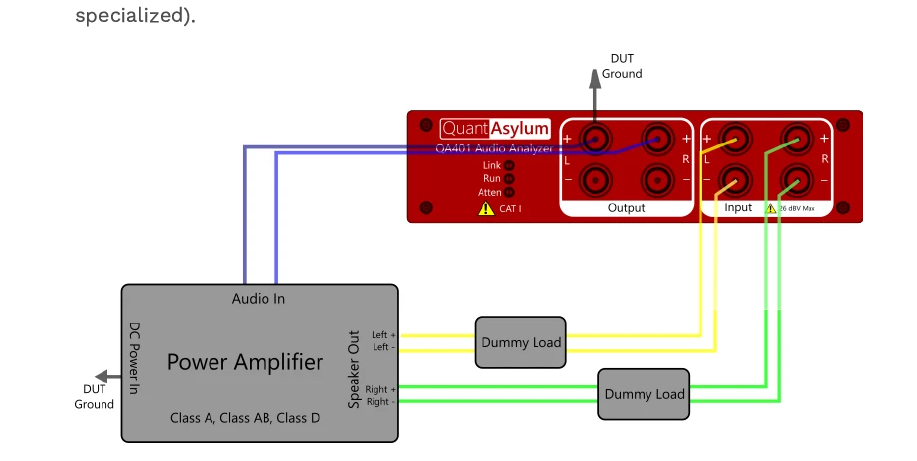
Update- I was looking at the “Basics: Power Amps” app note and noticed that I am doing what it says not to do, and that is I am not measuring differentially across each dummy load. The BNC shells for both the L+ & R+ connect to the respective dummy load “-” in my setup . For this particular amp, the “-” for each speaker is the same (circuit ground), but it sounds like I need to make some new cables to do this measurement properly. Maybe that is why I only see the problem at the dummy loads… Will update later…
and connecting the DUT ground to a grounded sig gen I was able to get some much better results all around, particularly when measuring the THD/SNR from the Phono stage to the load:
At this point I am not sure if there is something going on with the DUT or the FR measurement through the Phono input- will do a listening test with a phono hooked up next. I may also look at the the THD/SNR of a few more points as well…Oh, if you are curious these are the BNC connectors I have been using to make my cables- in this case just the center conductor was used:
I have never looked at anything in the time domain with the QA402, but will do so later. I have not measured anything today- I guess I need a 402 fix for the day- will report back later. Thanks for getting back with me as always.
Are you sure your NAD amp doesn’t have a fault with its 0V and/or grounding? The NAD I mentioned above originally had a fault that caused excessive noise and it turned out to be one of the 0V jumper wires had a dry joint which caused part of the input circuit to float - which links back to Matt’s point about no ground. I was not impressed with the quality of the pcb or soldering in the NAD3020e.
While I looked at the solder joints at various points at the circuit, I did not check the phono ckt extensively for bad solder jts. I am not holding up a lot of hope since the phono stage works great up to a point when the volume control reaches a certain point- I don’t see why it would make a difference from the schematic, which I am posting here:
I need to listen to some records, but have company now and so it may a few days before I can do that and if there is a lot of hum them I will look at the solder joints…
The other thing I’ve been doing for a long time, that you appear to not be, that has greatly helped me is plugging all devices into the same power strip. That way the earth grounds are solidly consistent at least at the AC interface to everything.
Thanks for the suggestion. My PC is plugged into a UPS (the UPS side), and the Sig gen ground is plugged into the outlet which the UPS is plugged into. The wallwart for the powered usb hub which the QA402 is plugged into is plugged into the “surge” side of the UPS. The integrated amp, which does not have a ground terminal, is also plugged into the UPS. I can easily enough plug the sig gen into the UPS. But I will do a listening test with the integrated amp hooked up to my phono- maybe even later today as my company has left for a bit…
Try putting a power strip off the UPS (where your PC is connected) and plugging everything into it. That way you are guaranteed the ground potential is the same.
The problem with that is then my PC does not have the protection of the UPS, though I don’t know how all the PC power supply grounding is as it relates to the USB power supply conversion on the motherboard.
we can see from your freq domain plot that around 500 Hz things are looking crappy. With a 64K FFT and 96K sample rate, that frequency occurs in the chirp around the 120 mS time or so. In other words, the weird thing that is happening at 500 Hz in the frequency domain must be happening around 120 mS in the time domain. Can you zoom in to different areas in the time domain? You should see the sine around this area showing about 2mS period. Cursors would be nice here, eh?
But what I think we’ll see is something strange happening to the recovered sine at this period in time.


 ). It is baffling to me. I will look at a new receiver I have with a phono input at some point in time, but this makes no sense… at least to me right now


 . For this particular amp, the “-” for each speaker is the same (circuit ground), but it sounds like I need to make some new cables to do this measurement properly. Maybe that is why I only see the problem at the dummy loads… Will update later…