Hi All,
Currently I have been making a THD and THD+N using a single ended connections between the output of my amplifier through a custom T-pad attenuation circuit of approximately 33dB.
My question is.
If I wish to make differential measurements from the output of my amplifier to the QuantAsylum QA401 using the attenuation circuit described above I’m going to need two of them. One Attenuating the speaker positive and One Attenuating the speaker negative. Both will use the same resistor values and will connect to the differential input on the QA401.
Is that correct or do I need to go about it a different way?
Hello,
since I have some experience doing such measurements with the external attenuator, I’ll can share it.
Theoretically, your idea will work, but you can expect bad CMRR.
The example article: https://e2e.ti.com/support/amplifiers/f/14/t/848102
I achieved more than 80dB CMRR using 10-turn trimer resistors for the attenuator, alligned with the QA401 input (very short and simple):
- Connect your attenator as close as possible to QA401 inputs.
- Decide will you use internal 20dB attenuator or not. The alignment works either for w/ or w/o internal, but not for both cases.
- Bring the very same input signal to the both (+ and -) inputs, then, adjusting the trimers, try to get the smallest possible levels in FFT view. Try with sine 1kHz, perhaps triangle too.
Hi Zoran,
Thank you for the response.
This is my current setup and my current results. I would like to try and remove and common mode noise.
I must admit I have not taken many differential measurements in the past but surly a CMRR of 80dB
is better that using a single ended input.
I don’t quite understand your point 3.
Why do you bring the same, input signal which I assume is the speaker + positive output to both
the (+ and -) inputs?
Just to be clear, I thought that to take a differential measurement I needed to have one positive signal going to the + or non inverting terminal of the QA401 and one negative or grounded signal going to the - or inverting terminal of the QA401.
Then the differential action of the op-amp inside the QA401 would remove any noise that appears on both the non inverting and inverting inputs as they are in phase and so cancel out.
This is what I was thinking that I will need two attenuation boxes. One for the non inverting (Speaker +) and one for the inverting input (my signal ground). This will then attenuate any noise by the same amount so it is later rejected by the differential input. And yes keep the leads very short from the attenuation boxes to the QA401 inputs.
If you could provide me with some more information that would be very much appreciated.
For completeness here is a link to the L-Pad attenuation calculator that I used. I made a mistake in my first post I said T-Pad. Sorry about that.
http://www.sengpielaudio.com/calculator-Lpad.htm
I measured the input impedance of the QA401 to be about 98.985K
I have also attached the formula to calculate the Rs and Rp resistors.
I wonder if using the L-Pad attenuation would improve the CMRR.
I have also include a YouTube link Volt Precision Reference & Hamon resistor network
12:40 time stamp. This shows how you can increase the accuracy of your resistor divider.
Is what I’m trying to possible @matt
Kind regards
Stuart
Hello Stuart,
Step 3 is for calibrating your attenuator to get best possible CMRR, aligned to specific QA401 input.
Bringing the same signal both to positive and negative input you expect to get zero differential input, but this will never be the case, because of unbalanced attenuator network. By trimming resistors in your attenuator, you should try to get the lowest levels possible.
For example, bring 0dBV 1kHz signal of the same polarity to both positive and negative QA401 inputs, and do the FFT. You’ll get 1kHz level of maybe -70dB. Try the same with the internal QA401 attenuator.
Now, bring 33dBV 1kHz signal of the same polarity to both positive and negative inputs of your attenuator, having attenuator (+) output connected to QA401 (+) input and attenuator (-) output connected to QA401 (-) input. If you get the same FFT 1kHz level as before, you attenuator is perfect by itself. Trimming resistors in attenuator you should get at most -80dBV, perhaps even less.
Finishing that, you attenuator will be ready to be used in the usual way.
If you still have trouble with my explanation, let me know, I’ll draw a schema for you.
Is your speaker black output on the same level as input GND?
Some amps have bridged outputs.
Also, some amps have DC offset between input signal ground and outputs.
After calibration, measure the 0dBV 1kHz signal with and without this attenuator. You’ll find out exact level of attenuation, enter that value as external negative gain in QA401.
To minimize low freq EM noise I strongly suggest using twisted pair cables as on drawing.
Hi Zoran,
Thank you so very much for your time and excellent explanation I truly appreciate it.
I believe that what you have sent through will really help me to maximize the measurement capabilities of the QA401.
My RCA input or signal input has a 4.7ohm resistor between its signal ground and the speaker negative or speaker ground. This raises the signal grounds node a little reducing noise on the input as I’m sure you are aware.
As I was only using a single ended input to the QA401 I didn’t want to connect the amplifier end of the shield from the coaxial cable directly to the speaker or signal ground as I was afraid that I could make a ground loop. So I wanted to rely on only one ground reference that being the signal ground.
So in my mind I thought that as the QA401 is isolated from my mains or laptop supply ground I can set its ground reference from my signal ground when I connect the signal input, from the output of the QA401.
On your schematic/ diagram, you show the amplifier end of the coaxial cable as not connected to anything. I did not know that you could do that. I thought that it had to be connected to something so it would allow stray noise to have a path. So I connect that end to my signal ground through a 100ohm resistor.
I have ordered some twisted pair cable so I can make a differential cable from the output of my amplifier to the attenuator connected directly to the QA401 as you have shown.
cabel
Your attenuation circuit and pcb idea is awesome I really like the pcb mount BNC connectors. I’m going to order some from digikey along with some precision resistors this weekend. I will then make a prototype pcb and then draw up and get made some PCB’s from china once I settled on a circuit.
Thanks again.
If you have anything else to add Zoran, I would once again be truly grateful.
@zoran4afc,
Just wondering were you got those fittings from can’t find the male BNC pcb mount on digikey
Can you please help me out.
Blockquote
My RCA input or signal input has a 4.7ohm resistor between its signal ground and the speaker negative or speaker ground.
If that’s internally in your amp, then OK. To avoid ground loops, don’t connect anything like that externaly.
Blockquote
So in my mind I thought that as the QA401 is isolated from my mains or laptop supply ground I can set its ground reference from my signal ground when I connect the signal input, from the output of the QA401.
Exactly what I had in mind.
Blockquote
On your schematic/ diagram, you show the amplifier end of the coaxial cable as not connected to anything. I did not know that you could do that. I thought that it had to be connected to something so it would allow stray noise to have a path. So I connect that end to my signal ground through a 100ohm resistor.
That worked for me perfectly. Try with and without 100Ω, see what’s better for you.
When 50/60 and 100/120Hz harmonics drop to noise level, youl’ll know that you did good job.
The STP cabel you ordered from ebay looks very good to me too.
In my experiments, using twisted pair cable I got more that 20dB better noise rejection that with usual audio cable. Compare different cables by moving them in different positions while measuring FFT. With STP there will be no or small difference of cable position, even if you make a loop of it.
I am using STP cable for unbalanced (RCA) connection also. I connect negative wire to both ends signal GND, and shield to source GND only.
The 1% resistors will do just fine, since you are using trimming resistor anyway. The temperature stability is much more important. Don’t go over 10k, it will add noise and instability. On the other end, lower R values implie larger current, therefore more heat and temperature instability. The resistors should be as close as possible together on the PCB, native dissipation several times larger from expected in your circuit, SMD if you can find such, good quality metal film and 10-turn trimmer.
Hi @zoran4afc,
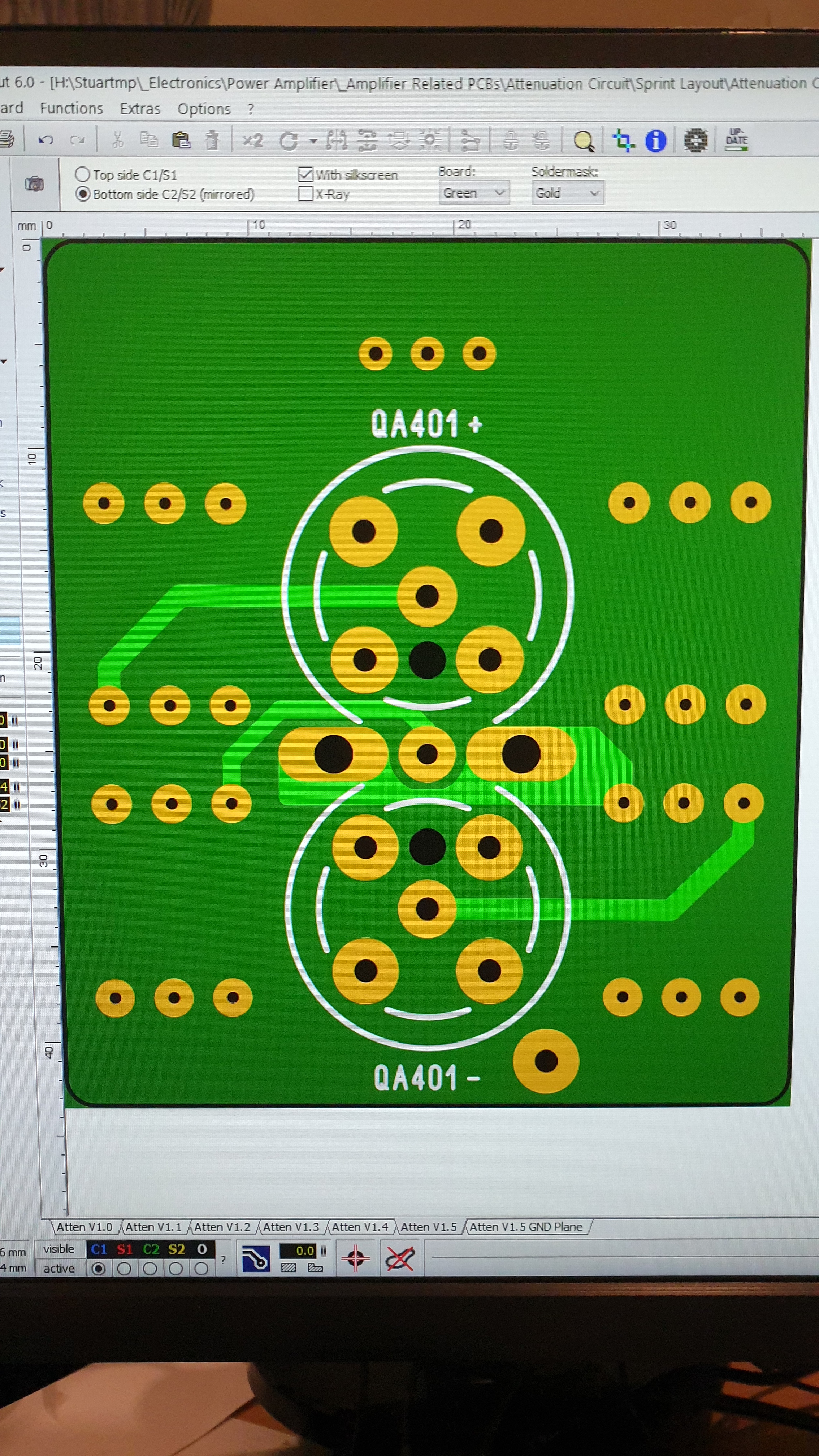
I have drawn a pcb using the same fittings that you have shown and will get it made in china.
One question I have is should I use a ground plane or not?
Top side
Under side
Thanks again for all your excellent advise.
Stuart.
I didn’t and I wouldn’t use ground from amp to QA input. It will only produce ground loop, since GND is already connected from QA output to preamp (or amp) input). As I already said, you can try and compare results.
Also, all resistors should be as close as possible, to ensure the best temperature stability. The absolute precision of resistors is not very important, only relative is. If all resistors are on the same temperature, they absolute values will drift together, preserving the ratio of the values.
Big symmetric holes between plus and minus signals tend to act as antenna.
Before making the custom PCB it is good idea to create the similar layout on universal board, to ensure that there are no unwanted effects I just mentioned. SMD is an optimal choice for that reasons.
Anyway, your circuit will likely perform good. If not, you can solder the resistors “in-the-air” directly from connector to trimmer.
Hi @zoran4afc,
Thank you for taking the time to make comment on the PCB.
I have taken on of what you have said and have revised the PCB’s
I have included both through hole and SMD.
Top
Bottom
Unless you can see and real problem with these I will get some made.
I’d be happy to mail you one and share the gerbers if your interested?
Kind regards
Stuart
As I said, your layout is probably OK.
If you are aiming for the best theoretical results, you really don’t need 12 resistors, only 4 are enough, since you’ll not get better precision from more resistors, but all four of them should be on the tight place, as close to each other as possible. SMDs are preferred for the reason of close placement, but you should get the big resistors for 10kΩ, SMD size 3225 (0.5W) or bigger, and place them tight to other resistors and trimmer, to distribute heat from 10kΩ resistors over all of them.
Thank you for your generous offer to mail one board to me, I’ll let you know the address .
Hi @zoran4afc,
Thanks for your concern regarding the power dissipation etc.
I believe that for me the power dissipation levels are very low.
See the attached table. I’m aiming for a final attenuation of 33dB
Also, I guess if you only want to use 4 resistors you can just install jumpers across the unused resistors.
I have now submitted my order with JLPCB and expect the PCB’s to arrive in about 9-12 days
I’ll keep you posed. PM me your address and I’ll send you some as I ordered 15 for only $7.50
I wouldn’t use 100kΩ resistors for R1. They will add several dB to the noise of attenuator, and the attenuator will be 10 times more dependent or internal resistance of input stage of QA401. I already recommended 10kΩ as optimal values for R1.
Additionally, the QA401 input is AC coupled: the input stage resistors are behind 33μF electrolytic polarized capacitors, so your calculation of exact attenuation will vary precision across the QA’s frequency range; the larger R1 => less precision.
In order to minimize temperature drift, the native dissipation of resistors should be 4-5 times larger than expected power at resistors.
When DUT are D-class amplifiers, they often have large DC offset common mode voltage relative to the signal GND - I measured some amps having -15V, the other +25V. That offset will add to dissipation, and I also had to replace the internal 33μF polarized capacitors with 10μF polyester - not an easy thing to do.
Hi @zoran4afc,
Thank you for that advise on using a 10K as the Max for R1.
I did however build a 97K and 10K version just so I could compare.
-
- The original single ended attenuator to the new single ended to differential attenuator.
-
- The 97K differential attenuator version to the 10K differential attenuator version as you suggested.
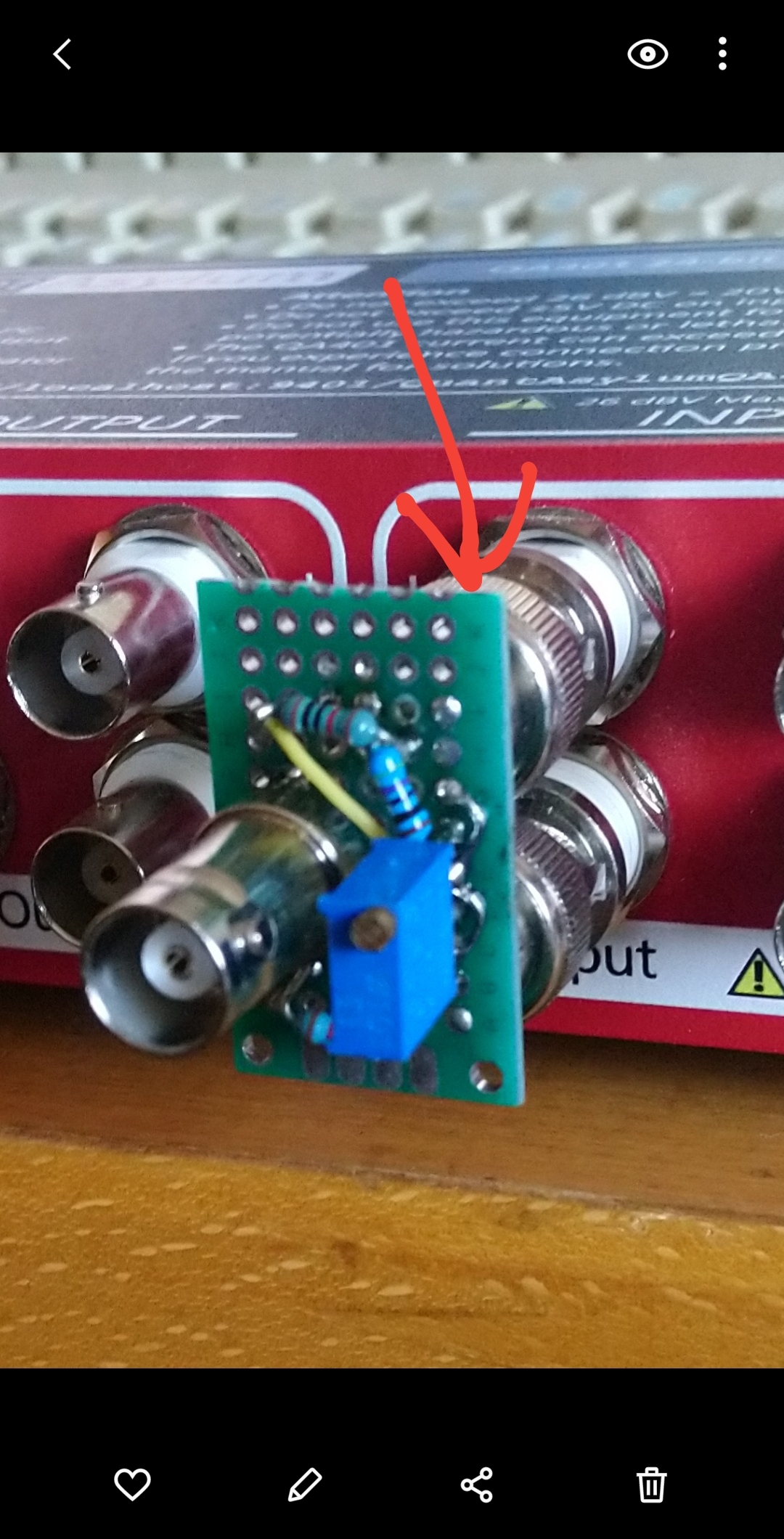
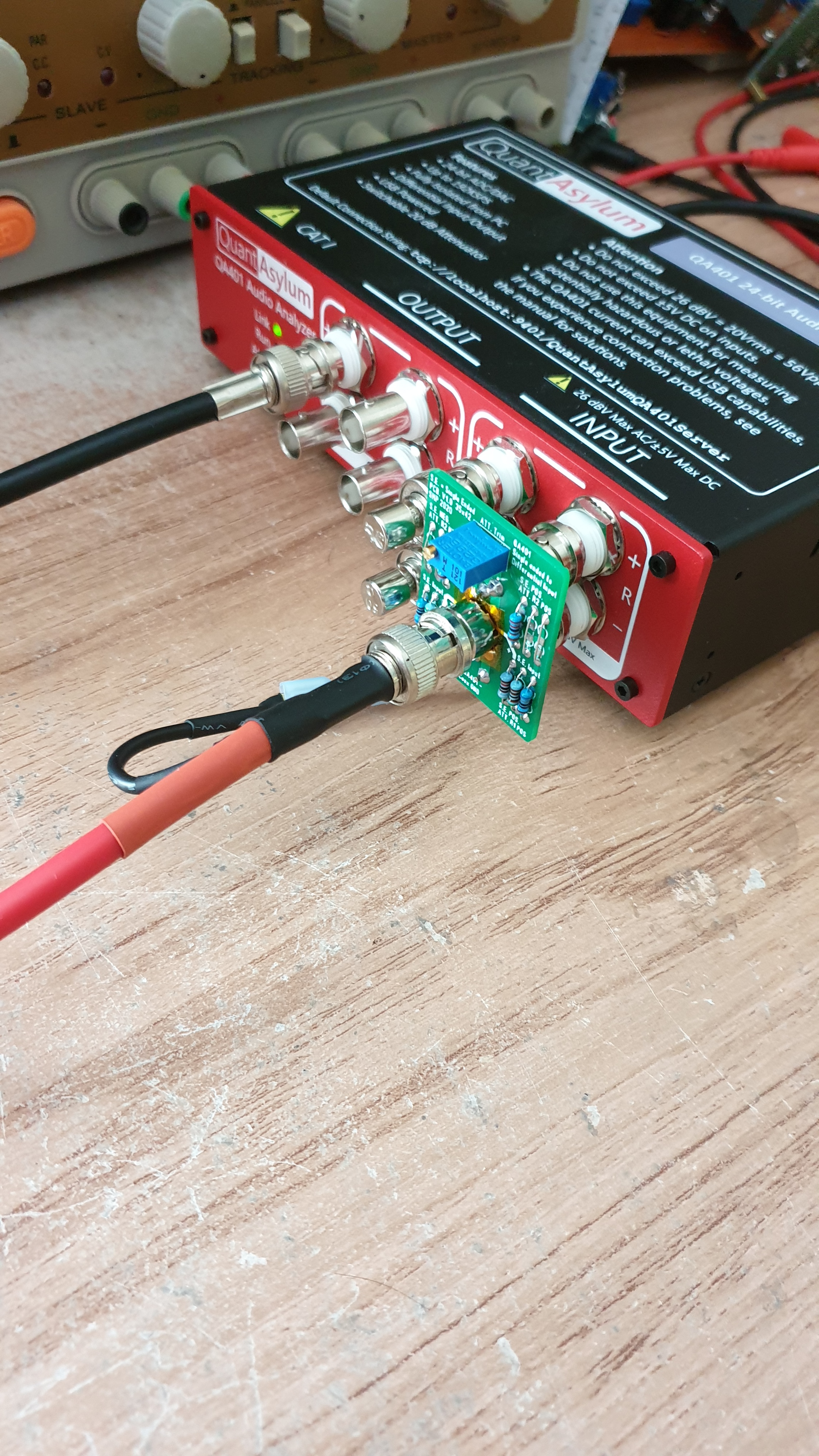
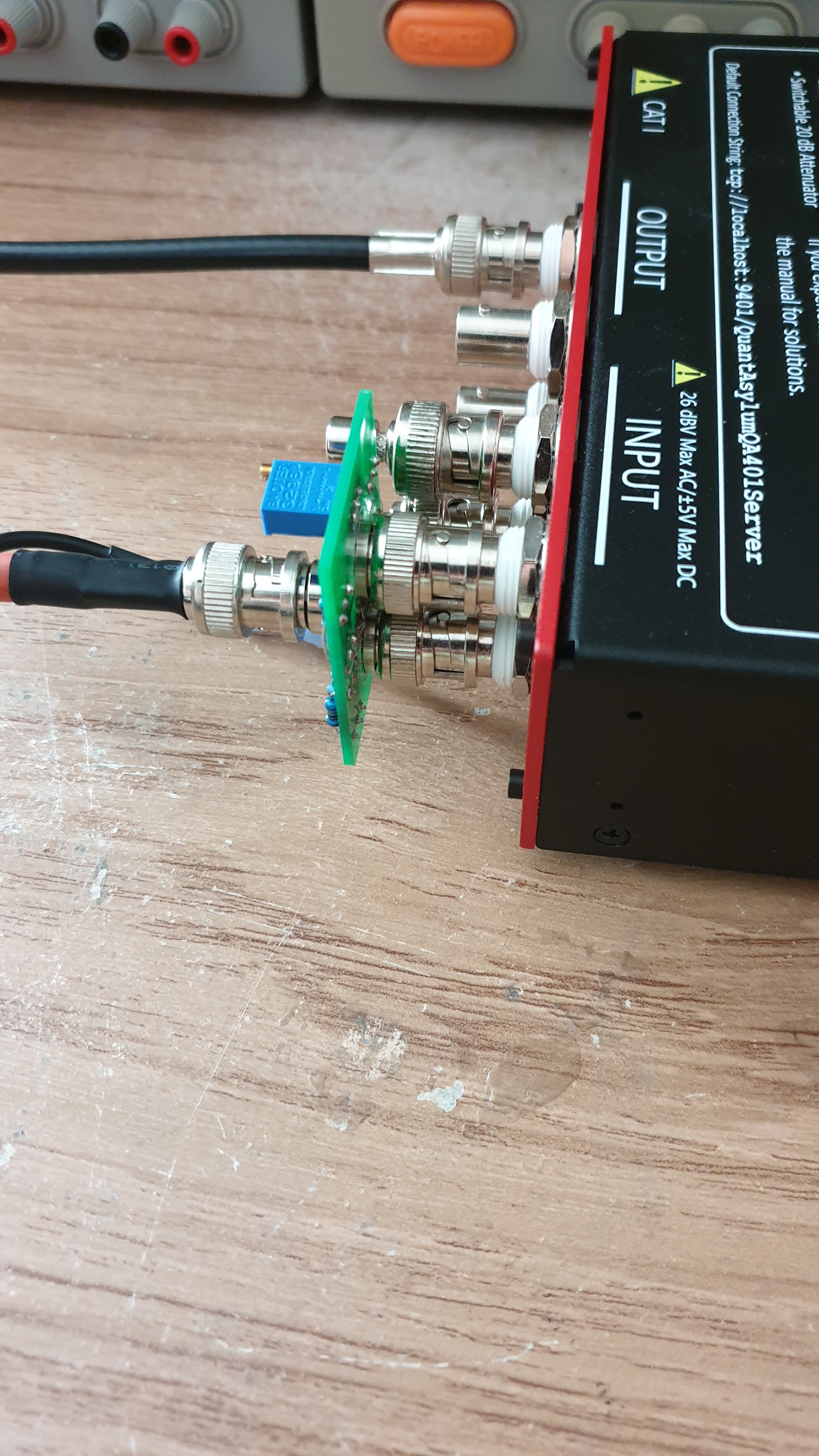
Please see the attached photos of my setup.
I also found I had lower noise by attaching the ground wire of the single ended connection to the ‘signal ground input’ via a RCA tee to my amplifier instead of to the ‘speaker ground / speaker negative connection’.
Single ended to differential input attenuation board connected to the QA401
Please note the cable used was
Canare Twisted Pair Microphone Cable - Balanced -L-2T2S
97K Version
10K Version
The numbers aren’t a lot different between the 10K and 97K version.
However there is definitely noticeably less noise in the plot around 20Khz using the 10K version
Thanks for your help.
Don’t forget to PM me your address details.
I would love to hear your comments of the results.
Hi @Stuartmp74,
Looks good, congratulations!
You can also make reference measures, for comparision.
- QA401 back-to-back with the attenuator
- Your testbed, amp powered off, all signal and power cables connected
- Your testbed, signal generator off
Also try to move Canare cables in different positions, loop it, bring closed to power transformers and PSUs and see if there is more or less noise. Use AVG=0 for faster response, then change to AVG=6 (I didn’t see much benefit of AVG=20, just very long measure cycle) when you notice something odd.