Thanks for the reference, that’s an interesting discussion!
You are correct, I do single ended measurements here.
The signal ground, the chassis ground and the speaker negative leads are all the same on the amplifier. The amplifier is a floating design, with only 2 leads on the mains cable. I have mostly done my testing with the oscilloscope, looking for visible distortion based on the input from a function generator. Both connected to earth ground. And to make sure the issues I saw was not related to earth ground I also did the same tests with a battery operated scope and generator. The results looked the same.
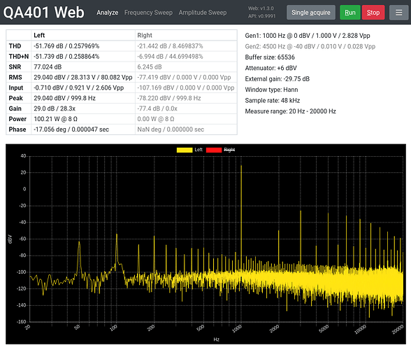
The next step was connecting the QA401, and I needed to step down the voltage a bit.
I have now put my circuit on a perfboard, so I’ve done some more testing. These are all with the QA401 in loopback (no amplifier).
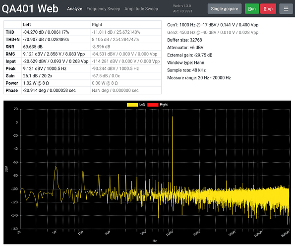
First test is the same as my second post, first picture, except this time with the perfboard:
This shows a noticeable improvement to the right of the fundamental, though the numbers don’t change all that much.
Next test was using a BNC to dupont adapter instead of the BNC to grabbers on the output of the voltage divider:
That was actually a big improvement. I tried switching it around, using dupont on the input of the voltage divider instead and it was back to the previous result.
Third test was doing a differential measurement:
The results look slightly better.
And the last test is that I replaced the BNC cable on L+ with a small BNC adapter that lets me plug the dupont adapter right on the input of the QA401:
It got slightly better now as well.
I only have 1 of those adapters, so maybe it would be even better if both the L+ and L- used the adapter instead of a cable.
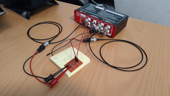
Here is what the final setup looks like:
There are so many little details that all have different effects on the result here. Not too bad now though!
I will do some tests using this setup on the amplifier as well, when I get the time.


