We are facing trouble in testing a 1000 W power amplifier with the QA403. The website directs to use a dummy load made of power resistors of 8 ohms with -14 dB attenuation, but as we are running short on time, we decided to move on with the speakers. But then next issue arised, we are not sure of the connections. The speaker is rated 8 ohms, but cannot provide enough attenuation through by pass. A help here, would be much appreciated.
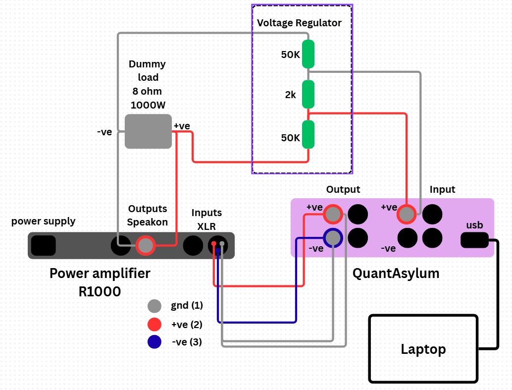
Here, we attach the first version of the test circuit we sketched. DL which is the dummy load, connected across the power amplifer is then connected to a typical voltage dividing circuit made of two resistors 100 K and 2K to obtain a voltage drop of 1:50 ratio.
The problem with that attenuator topology is it only adds 6dB extra headroom if the amp is single-ended, whereas separately attenuating each speaker terminal with a resistive divider to ground and taking a differential feed from them can add lots of headroom whether or not the amp is bridge tied or single-ended.
Put another way centre-tapping your 2k resistor to ground is worth considering…
Note that ground currents flow through the attenuator if modified as I describe, so you have to pay attention to ground layout/routing.
I see some points which must be considered for using the QA403 in such a setup.
Is the balanced input of the amplifier electronic balanced or is it isolated with a transformer? This is important because the shields (= grounds) of all BNC connectors on the QA403 are connected. So the outputs and inputs on the QA403 share the same ground.
In case of a single ended power amp, the amplifiers negative output is typically at ground level.
In case the amplifier has an electronic balanced input and single ended output, the input ground (pin 1 on the XLR) and the amp negative output are at the same level (probably with a few ohms for ground isolation).
The voltage divider design 50k - 2k - 50k only makes sense for a balanced amplifier output stage. I would rather propose a single ended -20dB divider such as OUT+ - 10k - 1k - GND. The QA403 measures the signal across the 1k resistor.
On checking my QA403, all BNC grounds are connected together.
It then means that the top 50 is grounded on both sides and is not part of any voltage divider.
I suggest to use the QA403 input in differential mode across the 2K resistor. But, in order to get a known attenuation it must be remembered that a differential reading gives a 6 dB gain. A 40 dB attenuation should require replacement of the 2K resistor by a 1K.