Attached is the image of my current setup for testing after followed “Basics: Power Amps” document . On page 4 of that document it mentioned “For the amp output, however, we don’t want to make a ground connection”. Does it mean I need to disconnect the ground connection on my secondary output transformer winding? Since there’s a feedback from my secondary output transformer to the first stage of the tube amplifier it required to have ground connection there. Please let me know if any correction is required from the diagram before I proceed with the test. Just want to make sure I hooked up right the first time.

You just have one ground connection, the shield of the coax going to the amp’s inpuit? Then it should work.
The differential connection from the dummy load doesn’t need any ground connections as its differential.
MarkT,
Thank you. However, what I tried to know is that can I leave my secondary transformer winding ground connected as shown? As I understand the secondary transformer winding is required to have ground connected since it has feedback.
The question here is do I need to disconnect the Ground from output transformer secondary winding or it’s OK leave it there with this set up?
Have only a single ground connection between amp and QA403 then there won’t be a ground loop. The amp’s input ground is probably the best place to do this as its the most sensitive end of the amp. The amp’s input and output grounds may not be exactly the same due to currents flowing.
I assume the amp’s ground is connected to earth like it should be?
Yes, the single star ground point is connected to the amp chassis safety ground. My concern is that I can’t leave my output transformer float since it has a feedback going back to the first stage of the amp. If connected as shown then the negative (center pint) Input of the QA 403 will eventually connect to the ground since I used the jumper J9 on the load board for Unbalance connection. Will this be a problem with a short from center pin to ground on the Input of the QA403?
You definitely can’t let your output transformer float! You are sensing its output differentially, so don’t need ground connected as I mentioned, so long as there is one ground connection between amp and QA403. I don’t know anything about jumper J9 - you’ve not included a schematic of the dummy load board.
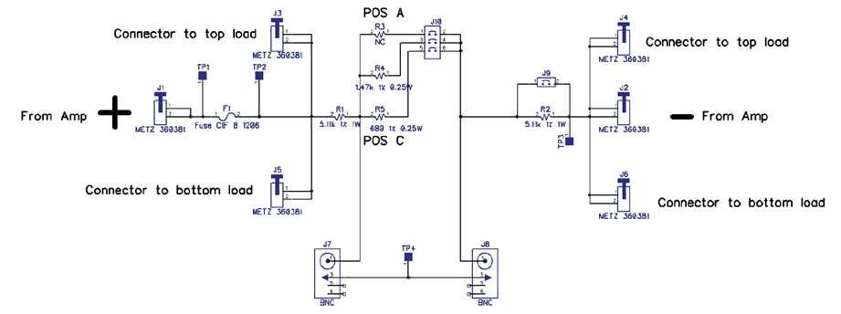
The J9 mentioned is reference from dummy load board that was fabricated from “Measuring Power Amps” document (see attached schematic). Also updated is more detail on the set up. I hoped this will clarify my confusion.
In “Basic: Power Amps” document mentioned that we want to measure differentially across the load to get the better CMRR. It also mentioned we don’t want to make the ground connection on the amp output because of the ground loop. As you can see from the diagram the center pin of - Negative Input of QA403 eventually connected to the Ground through jumper J9 since we tested in unbalance for tube amp. If connected as shown does it defeat the purpose of differentially measurement? or does it causes any damage to the amp or the test equipment? Also if we connect the oscilloscope across the load do we have to use differential scope probe?

jumper J9 needs to be present since the amp has single-ended output - you’d remove it for a bridge-tied or class D amp.
So for single end output set up I can use a standard or regular oscilloscope probe (not differential probe) to measure across the load, right? Just want to make sure. Again thanks.
Indeed, its single-ended. For accurate distortion meansurements using the QA403 you need differential mode as the output ground won’t be exactly the same as the input ground due to IR voltages in the ground wiring. Those IR voltages may be distorted even if the output isn’t.
I need some help with this setup and the software setup. I am going to give it one more go, and if I get crazy results, I will post them. This is not the unit, I am sure it is me. I am getting wattage readings of like 1 KW on a 45 watt amp. I have the correct impedance and I think attenuation settings. Very confused. Like I said giving it one more go and I will post results.
I do like the unit more and more every day…
I’m also confused by this circuit and the explanations given.
This indeed looks like it’s measuring the output of the amp in single ended mode. How would you modify the circuit to measure the output differentially (and take advantage of the QA403’s better noise rejection)?
The output of the amp is going to +ve and -ve QA40x inputs, so its measuring differentially. In particular it is seeing what the speaker coil sees, and immune to any noise or signal present between the amp’s input ground and output ground.
In my situation as shown in the diagram, I am not sure I can take advantage of measuring differentially since my output transformer secondary 0 reference tap required to connect to the Ground because of the Global Negative Feedback (GNF).
Attached is THD for a prototype 50W KT88 UL pushpull amp using above setup. As noted for low frequency end less than 60 Hz it did not perform good with output level of above 10W. I believed about 10W level is where the Class A ended in this prototype and it starts to transition to Class AB. Since I don’t have anything to compare I am not really sure if the result is normal and I set up correctly. Would greatly appreciate comment/input on this.

This may or may not help you, but it’s from a Pioneer Sx110 receiver (~1971) that I just measured the other day. It uses 7868 tubes in push pull configuration and exhibits the same type of poor thd at low freqs. It has quite a few of the original caps in it still.

The rise in LF distortion comes from the output transformer but all transformers exhibit this behavior. Your amplifier measure pretty good for a tube amp!
I gotta agree- it’s good alright for a transformer coupled unit.
Hey Scott, can you share your settings screen for that test? You’ve got great resolution there. How long is each sweep taking? PS Merry Christmas to you! Cheers, John
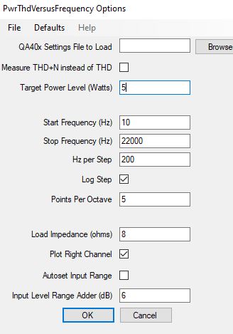
@restorer-john Thanks and Merry Christmas to you! Here are the settings for the main panel before I go into the PowerThdVsFreq automated test. I try to set receivers, intg amps and amps with volume controls for 25dB of gain and start off at 5w/8ohms, and then adjust the attenuator before going to the next power level, though the routine may do that as well. I overshoot the frequency range and just show 20-20khz most of the time. It might take two minutes to do a sweep. One channel is getting another NOS 7868 tube and should look better after re-testing. Will be in an upcoming video at some point…

1 Like