Hi Matt,
Is there any way to load a FR trace into graph tool without having to run a sweep first? Whenever I load a saved FR trace, the X-axis displays as linear?
From the QAAnalyzer app you can launch an empty graph tool (pic below) and then load a previously exported trace. But you are right, there’s not a way to specify log and it defaults to linear. Will fix for next release.

I’m trying to export and then import traces into graphtool, but they still have a linear x axis. Is there a fix for this that I’m not seeing?
Also, is there a more direct method to get a measurement into graphtool? If not, I suggest a “save as trace” button or something similar to make this process fast and easy. I and most of the engineers that I know tend to use lots of overlays to compare the system behavior in different states / inputs / levels, etc., so making this efficient would be a big help.
Also, please make the multitone, white noise, and frequency response generator options mirror-able. For example, I’m testing soundbars. These have no analog inputs, rather usually just a single HDMI. So, it’s very convenient to connect the bar to the measurement PC for a closed loop measurement. The only workaround I know for the non-mirrorable signals is to open loop a noise signal, which is OK for small signal response but not large signal or level sweeps.
Hi @Clayton, all generators will be mirrorable in the 2.0 release. But that is still a ways out.
The workflow for accumulating traces on a plot is to keep measuring and keep adding them to the plot. It should be very, very quick already. For example, to measure the EQ response of an amp or guitar pedal, you can run the plugin AmpFrequencyResponseChirp with knobs centered, verify the plot is showing what you want. Then move the treble to max, press F3 (to run the test again) and add that to the plot. And then move the treble to min, press F3 again, and add that to the plot. And very quickly you have 3 traces on the GraphTool. Then adjust axis, tweak titles, add notes, right click and export as EMF and you get a vector graph to drop in word for your documentation.
Is that workable for you?
Hi @matt , that’s good news about the v2.0 feature. I look forward to it.
In the meantime, since there is no means to mirror the generator outputs, I have to measure open-loop. This means that the AmpFrequencyResponseChirp is not usable. As far as I know, the only method is simply to play noise on the device and run the FFT with a bunch of averaging. But, I don’t know how to get this measurement into graphtool without export to a file, and reimport, which is quite tedious if there are numerous measurements. Is there a better method? Ideally, the measurements would handled in the main measurement window, rather than needing all the extra steps to get them in to graphtool. But, at least a streamlined method to get a measurement into graphtool would be great addition.
This leads to a couple of other feature requests:
- Most noise signals are pink noise, so it’s very convenient to display this in “RTA” form, so pink noise input yields a flat frequency response measurement. I don’t see a method for this currently. White noise yields a flat measurement, but is a crummy input signal for open loop measurements due to tiny low frequency output, and is sometimes unavailable. For example, Atmos and DTSx signals are provided only as pink noise, so the measurement / analysis needs to be able to handle that ideally without post processing. That is, it would be quite handy to be able to compare QA40x measurements with AP measurements.
- With noise input, smoothing is essential even if a bunch of averaging is used. In the rare cases, periodic noise is available, where the sequence length can be adjusted to match the FFT size and yield a smooth measurement. But, most noise signals are random pink noise rather than periodic, so an unsmoothed spectrum will look very fuzzy without smoothing.
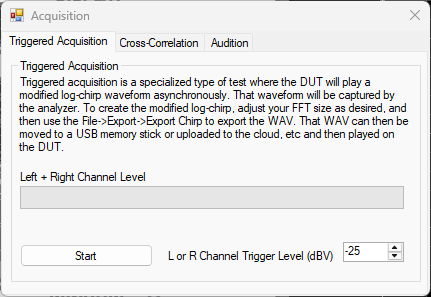
Hi @Clayton, have you tried Triggered Acq? Right click on the RUN button and you take a specially created WAV and put that on your DUT, and then play that back on a DUT. The QA403 will wait until the playback starts, capture the waveform, removed the “start” signal and show the spectrum. See setup screen below. Also see HERE
I think a chirp for measuring rooms and/or speakers is much more appropriate than pink noise. Pink is 100% the right thing for in some settings (especially canned routines in AV receivers) because the power in a chirp at higher frequencies can potentially damage tweeters in marginal systems if you aren’t careful.
PS. I have never really understood smoothing/averaging when looking at a room. If a room measurement is showing deep nulls and peaks, they are legit and it’s a real problem (usually due to lack of room treatments). Smoothing them away makes the plot nice look nice, but doesn’t change the fact that the room has very serious problems. I have seen plots of rooms that look flat, but with a tone playing, you can move your head a few inches and hear wild swings in amplitude. That said, I do take your points about smoothing and pink being useful to be present and an option.