Hi everyone,
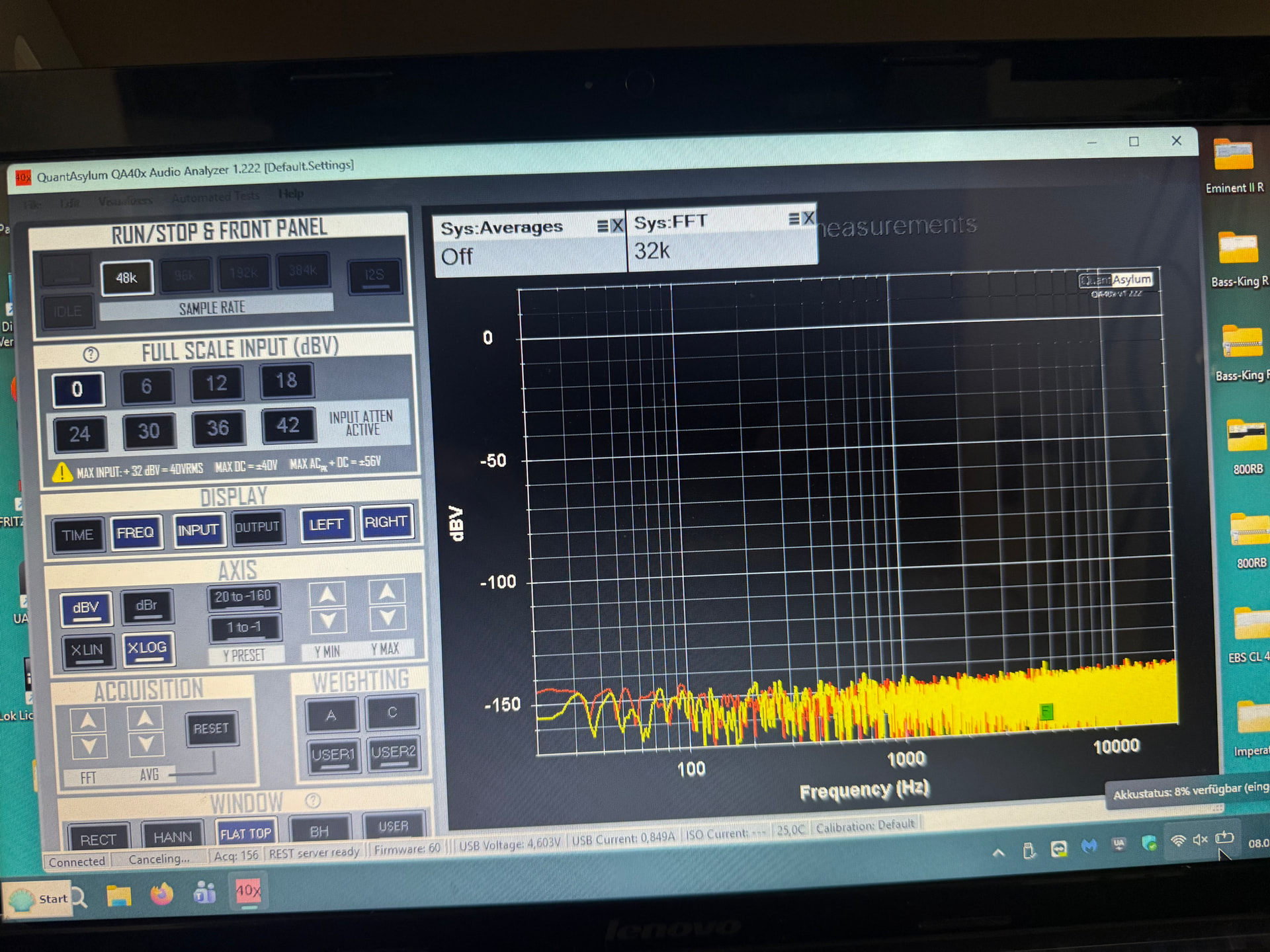
I am designing a tapped dummy load for high-power amplifier testing with my QA403.
My immediate goal is to test a 200W into 8 ohms amplifier (40Vrms). Because this hits the absolute maximum input limit of the QA403, I want to build an attenuation network with enough headroom to eventually test amplifiers up to 300W into 8 ohms (48.99Vrms).
Based on the QA “Power Amp Basics” blog post, I plan to split an 8-ohm total load into a two-resistor voltage divider to target an attenuated voltage of 35Vrms at the analyzer input.
Proposed circuit values:
-
R1 (Top resistor): 2.28 Ohms (Dissipating ~86W at 300W total power)
-
R2 (Bottom/Sense resistor): 5.72 Ohms (Dissipating ~214W at 300W total power)
-
Connection: Differential tapping across R2 to avoid ground loops.
This should yield a total attenuation of -2.92 dB, dropping the 48.99Vrms down to a safe 35Vrms for the analyzer. I plan to use parallel arrays of non-inductive power resistors on a heavy heatsink to handle the thermal load.
Are my calculations correct for this target? Is there a more optimal resistor ratio or alternative approach you would recommend for this power level?
Thanks!