Notice that the THD is shown as -89.8 dB while the THD+N is shown as -91.9 dB.
When the frequency is raised a bit, then the anomaly goes away.
Notice that the THD is shown as -89.8 dB while the THD+N is shown as -91.9 dB.
When the frequency is raised a bit, then the anomaly goes away.
Here is the second screen shot which would have been included previously except that I am restricted.
Hi @mhuth1776, what anomaly are you referring to? That the THDN is better than the THD?
Additional information - the circuit being tested is a TI x990 general purpose opamp configured as a 4th order Chebyshev low ripple filter with the -3db point at around 150 Hz. There are two op amps cascaded and the passband gain is nominally 12 dB.
Yes, the THDN < THD. That is what I see as the anomaly. I certainly don’t understand it.
It’s hard to know for sure what is going on. There’s a bit of a clue from the N+D measurement of -82.7 and with 5.35 dB peak, that should yield a THDN of -88.05. But your THDN is -91.09.
If you move to 1 kHz, does that issue resolve? There are slightly different bandwidths used for removing the fundamental in the code, and my guess is that the low frequency of 100 Hz is magnifying things (eg, the bandwidth in the THDN code path is more aggressive and removing much of the energy from 20 to 200 Hz (or more). And since your signal has a shelf from to 200 Hz, and then drops down as things go out to 80 kHz, the difference is magnified more.
You can play around with your GEN2 and add a stiff “interferer” at, say, 150 Hz. Set the step size to be 10 Hz. Note as you sweep the interferer around with the FREQ2 button, as you move close-in the interferer is at -80, but the N+D is reported as -96. So, clearly the interferer is being ignored as it’s filtered out.
As I move the interferer just beyond 200 Hz (100 Hz beyond the fundamental), you can see the N+D suddenly jumps to -80. Because the interferer is suddenly outside the bandpass, it now dominates the measurement and N+D now reflects the amplitude of the interferer.
Thanks, @matt . Seems like you have diagnosed the problem correctly as I did some poking around with GEN2 as well as at different frequencies of the fundamental. At this point, I’d say that there is a bug in either the software or firmware, as the FFT clearly has the information necessary to get the correct answer. My setup likely exaggerates the issue, as the noise floor is the 60 Hz power interference and related harmonics. These fall close to the 100 Hz measurement.
How does one report a bug to QuantAsylum? I haven’t found a support channel other than this forum.
Hi @mhuth1776, you can log a bug on Gibhub, but here’s fine too. The current plan is to move the QA401 hardware over the QA402 software (aka QA40x). The QA40x software will also run the QA403. So, the 401, 402 and 403 will share the same software.
The 40x software has some modes that are being worked on to help understand the issue you ran into. For example, you can see the plot below the which frequencies are notched out (white) in a THDN calc, and the fundamental and its bandwidth (red)
Zooming out you get a picture like this:
And in linear x axis it appears as follows. Note that with 100 Hz fundamental, you have a lot notched out.
And with a 1 kHz fundamental, it looks a bit less busy:
But, there’s still a burden on the user to understand the minutia. I think to “fix” this would require surfacing a lot of choices such as fundamental bandwidths and then harmonic bandwidths, number of harmonics to consider, etc. In other words, if you provide a lot of knobs, it would allow an expert to tweak precisely. But it could also result in a lot of users accidentally over-tweaking a good measurement to bad (or bad to good). The trick is how to balance. Your feedback here is very valuable.
Hi, Matt. Thanks for your detailed response. Happy New Year! Take the rest of the day off.
I’m sure you are quite busy with the 403 development. That’s an exciting new development and I look forward to it.
As far as the software problem is concerned, now that I understand what is going on I can wait for the 40x versions. In fact, I will offer to Alpha/Beta test it if that is something your company would be interested in.
I spent the afternoon in my lab playing with the 401. I settled in to look at it in loopback so I could characterize the needed bandwidths for the THD/noise filters to get accurate results. I concluded that the +/-50% around the fundamental is generally way too wide, although the “right” value depends to some extent on how far above the noise floor the signal is.
What would work well for me, and probably be simplest to code would be to expose the filter “Q” as a parameter specifying the number of FFT bins that are discarded from the noise. From what I saw with the 401, 11 total was the best answer for the 0 dB output that I had looped back. Symmetrical about the peak seemed to work okay for both flat-top and Hann windows. The other parameter I would like to have access to is the number of harmonics. The 401 is not really usable for THD measurements at low frequencies right now as a 20 Hz signal ends up completely polluted by noise as harmonics every 20 Hz are included out to 2 kHz leading to results of THD > 100%. I might be able to adjust the measurement width, but it seems easier to just constrain the harmonic count. There is space on the measurement setup pages if nowhere else for these two controls.
Okay, so how to make this foolproof? I’d say give up, due to the legendary ingenuity of fools everywhere 8-). You can make reasonable defaults with a restoration button. Twenty seems like a good default harmonic count, as that takes the typical 1 kHz THD measurement out to 20 kHz, and if I’m working on something exotic where I care about the higher harmonics, I’m probably smart enough to twist the knob, especially if I can see the harmonics on the FFT display. The filter Q is a bit more nuanced, although for the 401, 11 seems to get a full amplitude fundamental out of the way. You would probably want to add a couple for each additional 10 dB that the noise floor decreases. The nice thing about using the bin count is that the filter adjusts along with the FFT size. As for the harmonics, the same value would not be terribly out of line, although it would be better if the mask would narrow as the amplitude of the harmonic decreases. Of course, you’d want a button or menu to reset to defaults, which you have in a couple of places already.
There are actually simple algorithms that should be able to automatically adjust the filter and harmonic counts. For the harmonics you simply look a couple past where the last harmonic goes into the noise and that will probably be reasonable for “auto tune” mode. The Q is a bit more complicated, but again relies on finding where the signal disappears into the noise. One way to auto tune the Q for each harmonic is to simply look at the peak amplitude and use a predetermined adjustment to the fundamental Q based on relative amplitude. It is also possible to find the peak and follow it on either side until the amplitude slope reverses once or maybe twice. I expect that in most situations, this is good enough. A slightly more accurate method is to create a “mask” for each harmonic, which is just the output side of the generator. I looked at the “output” of the 401 in the program, and the shape of the FFT is exactly the shape that needs to be subtracted from the signal FFT to filter out the fundamental or harmonic. You just have to scale it to the peak of the harmonic. You only have to perform the substractions until you get to the noise floor or perhaps a bit beyond. This is the perfect task for the SIMD engines in most processors these days. You can do the noise sum and THD sum in the same pass or in a multicore pipeline, or in the GPU engine 8-). I wouldn’t worry a lot about optimization at first, though, as just exposing the two controls is a very welcome step forward, regardless of whether the computer can do the tuning.
Hi @mhuth1776, all excellent points. The graphics that show the filter bandwidths and omitted harmonics are a bit of a start in that direction. The harder problems come with signal sources outside the QA40x, where the oscillator quality gets really bad and the skirts get really wide.
So, in line with your recommendations, how about the following controls:
An override checkbox in the THD and THDN calcs. If ticked, the user can enter
I’m lovin’ that!
Thanks!
Hi @matt, I searched through the manual, but I did not find the controls or checkboxes for the THD and THD+N measurements. Where or how does one access those?
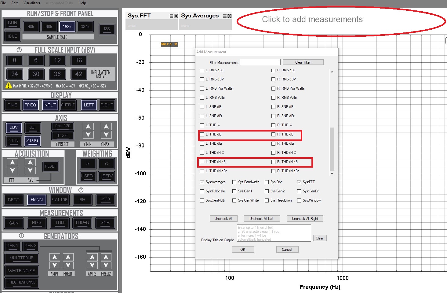
Hi @Gruesome. Click on “Click to add measurements” and select the THD and THD+N tile to add in the “Add measurement” window. Alternatively, click on the THD and THD+N buttons in the “MEASUREMENTS” section of QA40x. Right-clicking on these buttons will take you to “THD Options” and “THD+N Options.”
Thanks! I did not know you could right-click on those buttons (or rather, that there was functionality attached to that).
All underlined buttons can be clicked with the right mouse button to highlight certain features.
So, right clicking the underlined ‘THD’ in ‘Measurements’ in the left side menu brings up the usual start/stop frequency and fundamental selection method menu, not a menu that allows selecting the number of harmonics in the THD calculation, or the filter width:
(I knew about underlining indicating the presence of a right-click menu.)
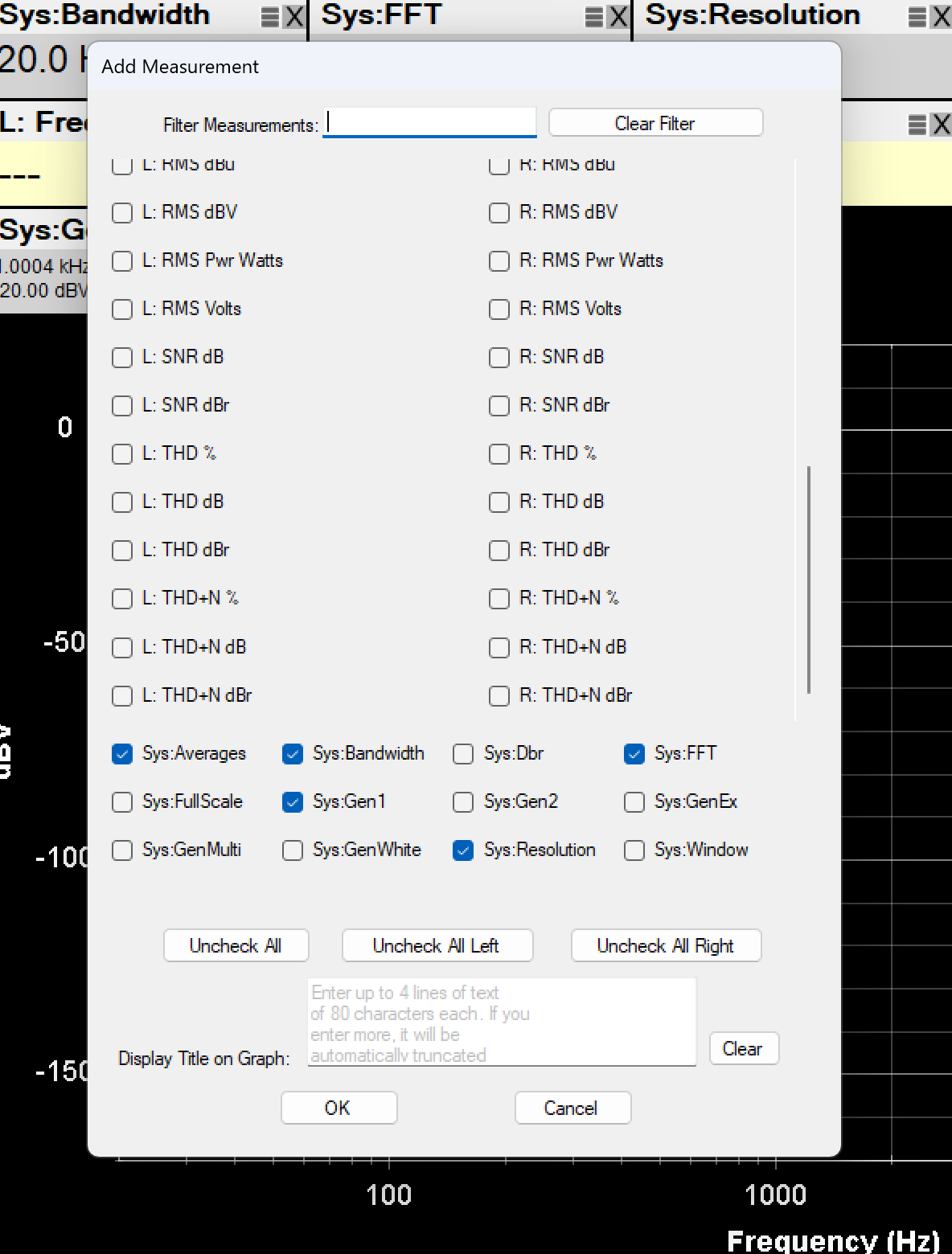
The buttons in the ‘add measurement’ selection menu are not right-clickable (and not underlined), as much as I try:
So, how does one get to those options? I thought as a last resort I could look at the code, but the github project does not have that.
You can only access what is displayed in the options window (THD Options). These are the options directly accessible from QA40x.
Thanks for chiming in, Claudio, but it sounds like you haven’t found the options I’m looking for either. I think I’ll wait for @matt ’s reply.
Hi @Gruesome, the options discussed above (number of harmonics) haven’t been implemented, but will at some point. Thanks!
I’ll wait for that then ![]()
Actually, as I mentioned in another thread, I’m not sure that looking at harmonics between 10kHz and say 80 kHz, while in principle very doable at 192kHz sampling, is the right thing. The two generator setup of QA40x can do two tone intermodulation; maybe that is a better way to assess amplifier distortion, and the relative magnitude of higher harmonics.
In other tests one now often sees exponentially spaced (evenly spaced on a logarithmic scale) multi-tone intermodulation test signals. That’s not something the QA403 can generate, or could it? The generators are software, right? So maybe there could be a program to generate 10 or 20 exponentially spaced tones, if I may put in another request.