It is also interesting that the L & R track almost exactly on top of each other
Perhaps the question should be, how can the QA help me diagnose the issue?
Hi. I believe that QA is not a suitable tool to diagnose the problems of an amplifier and search for the cause. The QA is a suitable tool to check the performance. Since you have been experiencing problems with amplifier performance through the QA, in my opinion, in order to make a diagnosis of what is creating the problem, it is better now to use other tools (oscilloscope, digital multimeters, etc.) to investigate what kind of problems there are that are generating the performance that you feel is unsatisfactory.
I respectfully disagree with you about the QA40x not being a suitable to diagnosis the problems of an amplimer. I use mine regularly for that purpose. I hook up a scope probe to one input (usually the left channel +) and terminate the - input with a short or load. The big caveat is to make sure you have the probe on the x10 position when measuring voltages >30vms. Somes I will have it do a frequency response sweep instead of using it as a spectrum analyzer. When making an adjustment for minimum distortion it is much easier to read it than eyeball it using a scope, IMHO.
3 Likes
VAR: Thank you. I just refused to believe that the QA could not be used in this manner.
What parameters do I need to setup on the QA403?
When making this adjustment for minimum distortion
Perhaps I explained myself wrongly. I meant that to investigate the causes of out-of-expectation operation of an amplifier due, for example, to the fact that the various voltages of the various working points in the circuit are out of tolerance for various reasons, and you have the service manual that indicates exactly the necessary values at the various points, it is more convenient to use other tools that allow immediate reading and possibly tuning of the amplifier and so on. Obviously, after that, one moves on again to the examination of performance by QA. All this is of course my opinion (but it is also my way of proceeding in these cases). However, it is probably me who is wrong. ![]()
Those values are DC and give no value to the Signal.
I guess you have never seen a Yamaha SM! ![]()
For years I have complained about horrible translation of languages and complete loss of meaning. When I worked for Siemens we called ir German / English
The item that I continue to bring up here is making this measurement, everyone has issues with what Yamaha is asking to be done. ![]()


I would agree- the 1st thing to check are the various key voltages (with a DMM) and if the voltages are reasonable, start checking from the input to where it looks bad ar disappears. A scope is fine to use for most things, but you are still going to need to apply a signal to the DUT and worry about triggering and so on, where the QA40x provides the source and if you are using the x1 probe setting, a really good indication of the signal level, plus if a stage is overloaded, you will see all the harmonics.
Once again, I think you are putting too much worry about doing this zero distortion measurement, unless you had to repair the output stage. Even then, your THD is 0.04% at 100w/4ohms. That is pretty darn good. I don’t know why you are having a problem- tweak the pots a little until you get the lowest THD if you want, but I would be very happy. Once again, I have found Hann filtering to work the best and I typically use 96k sampling and 64K FFT for most of what I do.
My only true concern is these Harmonic Spikes

AC ripple= AC voltage.
Just set your DMM to AC Volts (or rather MilliVolts) and measure between Ground and rails: you should get less than a One Volt AC.
I measure 0.000v with the DMM
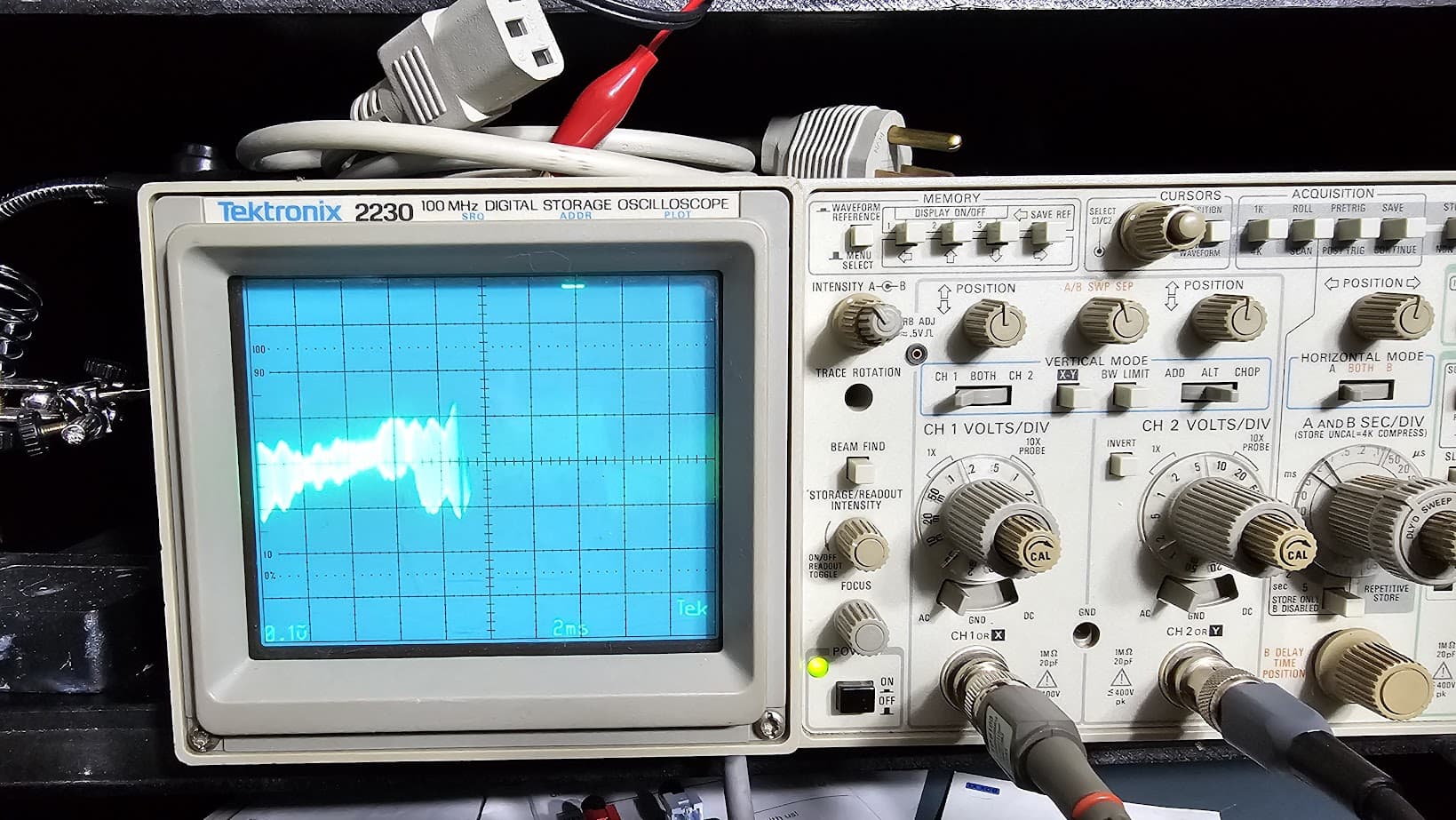
I measure 2vpp with scope
HB+

LB+
See post 60. comparison between unit #1 & unit #2
This is a very good answer.
The output stage was repaired.
Notice the shots between the two amps. #49 & #60


This is my 2nd M70. I will try to explain what is now taking place:
I am able to connect a scope probe to the DIST test point and adjust the DIST to a minimum value. No explanation of why this was not possible with unit #1.
Unit #2 has not been touched, yet it appears to test better
@VAR: Hi Scott, VERY interesting, I am looking to do exactly what you describe - use the Q403 while probing within a power amp stage to locate a mystery distortion source. Maybe I’ll start a new thread, we shall see…
Anyway, could you please clarify “Sometimes I will have it do a frequency response sweep instead of using it as a spectrum analyzer”? Is that as simple as you are just leaving the FREQ RESPONSE (i.e. Expochirp) generator running instead of the GEN 1 (single tone) generator?
Thanks!
-Steve
When I have connected one of the inputs of the QA40x to a Scope probe (the - input would be terminated into a short or 50/75ohm termination)- be sure you have the probe set to x10 unless you know your voltages are <30vrms to be safe- I apply a 1khz signal from the QA40x to the devices input and set the QA40x to look at the response from 20hz-20khz just I would for measuring the THD. The QA40x can be easier than using a scope since you don’t have to worry about triggering and can probably see smaller signals (at least compared to the scope I have). I think I use a 62k fft when I do this w/ a 96k sampling rate. I have used the frequency response (expo chirp) with a probe a few times when checking if there is a rolloff at a certain point.
2 Likes