Hi,
I’m using the QA450 with a QA401 analyser to test an A/B power amplifier and the frequency response is down around 1.5dB at 20kHz. I’ve been assuming it’s the amp but I just ran the same test replacing the 450 with an 8Ohm power resistor and there’s no significant drop off. Any ideas why this might be?
Hi @SimonA, the default setting on the QA450 is with the Class D “filterless” setting enabled in hardware. This is a simple first-order LPF with the corner set at 34 kHz in the output stage of the QA450. The purpose of this filter is the knock down the high energy in class D amplifiers commonly billed as not requiring output filters. TI goes into this in some detail in the link here. Around page 8 in the QA450 manual you can see the sweep of the QA450 and some more discussion on the topic.
The filter can be disabled easily if you can unsolder 4 0805 resistors and are handy with a screwdriver to open the case on your QA450.
Alternately, you could create a user filter in software to “undo” the first order filter response. This would involve making a short table in a text file that would offset what the filter is going and give you ruler flat response to 20 or 21K.
Let me know if either approach is interesting and I could provide more detail.
Thanks for the quick reply Matt… I think I’ll remove the resistors, if you let me know how to identify them that’d be great. The manual I’ve been using is the Jan 2019 Preliminary link on the product page. I’ve now spotted the reference to ah 34kHz low-pass filter but I can’t see a sweep diagram or any other discussion - am I missing something or looking at the wrong version of the manual.
@SimonA , the most recent manual can be found by going to Help->Launch Document PDF Viewer in the QA450 application (version 1.22).
To open the QA450, remove the two upper front panel screws. There are 4 front-panel screws total. But only two need to be removed. These are hex-head, and best done with a 2mm bit.

Next, remove the 6 side panel screws–3 per side. These are Phillips head. The case should lift off at this point. In the section of the PCB near the 4 output BNC you should see the following:
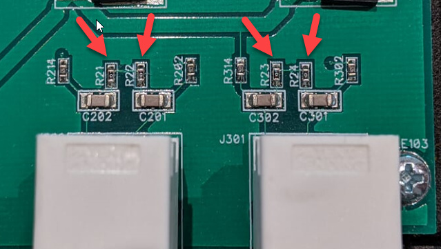
Above I mentioned removing the caps, but it’s better to remove the resistors. The resistors are 0-ohm jumpers and easily replaced. The caps are precise NP0 and not easily replaced. So, remove R21, R22, R23 and R24. Everyone has a favorite technique, but I prefer two soldering irons to remove parts like this. It can also help to add a bit of solder to each joint before you remove. If you have a single soldering iron, then it can help to hold the iron alongside the part and feed in more solder until the part flows off and sticks to the iron. Apologies for over-describing if you’ve done this a million times.
If you use a heat gun, be aware the white BNC are not thermoplastic and will begin to deform if you linger too long.
After removing, make sure there are no bridges across the vacated pads.
If you ever want to re-enable, then just re-install any 0 ohm jumper in those locations.
To re-assemble, just reverse the process. The case threads are fragile, so be careful you don’t overtighten. Leave all screws loose and in place until they are all mounted, and then gently tighten down to “barely snug” to ensure the threads aren’t damaged.
Let me know if you have any questions or run into trouble at any step and we’ll get you fixed up.
Perfect… thanks. If those are 0805s then I should be fine.