Amp Gain & Distortion Autoset Limit Issues

I am trying to run “Amp Gain and Distortion Versus Amplitude” and I am having issues with the AUTOSET INPUT RANGE since it is limited to a 30 dB adder, but my amplifier gain is more than 30 dB.

I normally use the AUTOSET INPUT RANGE and use a 6 dB adder as shown below for the “AmpThdVersusFrequency” test. The software seems to select the attenuation based on the Analyzer input level (DUT output level) plus my 6 dB adder. No issue there and the wording makes sense.

However, the “Amp Gain and Distortion Versus Amplitude” test seems to be adding the AUTOSET INPUT RANGE adder to the Analyzer output level (DUT input level). This is different than all other tests I have run across even thought the popup screen wording is the same and the 30 dB limit is causing me not to be able to use the AUTOSET INPUT RANGE functionality.

Thanks,

Dave D

Hi @DaveD. I tried running the “Amp Gain and Distortion Versus Amplitude” test and it seemed to be smooth including the operation of “AUTOSET INPUT RANGE” which is the margin that is added up to set “FULL SCALE INPUT”. I then tried to replicate your settings and saw that you set “TEST FREQUENCY” to 10Khz. When I set this value, I left the sample rate at 48Khz and tried to run the test. Immediately I got an exception that stopped me from running the plug in. I changed the sample rate to 96 Khz and everything worked normally. I wonder, did you by any chance set the sample rate to 48Khz when you run the test with the gen1 rate at 10Khz? If by chance that was the case, try changing the sample rate to 96Khz and see if, as happened to me, the test completes regularly with the behavior of “AUTOSET INPUT RANGE” regular. Below is the image of the exception that occurs to me

My issue with the AUTOSET feature is that for all tests it says the adder is to the input (of the analyzer or output of the DUT). However, for the AmpThdVersusFrequency test, I believe the adder is being added to the output of the analyzer (or the input to the DUT).

I ran some quick tests with and am using rounded numbers on the same amplifier that has a gain of 26 dB:

AmpThdVersusFrequency test:

Using a +6 adder:
-27 dB input to the DUT gave -1 dB output. Software selected 0 dB full scale range. See below. I believe the software should of selected the 6 dB full scale range (-1 dB output + 6 dB adder = +5 dB) as that is what other tests would of done.

-25 dB input to the DUT gave +2 dB output. Software selected 0 dB full scale range. Device had high distortion and gave me an overload shortly thereafter. See below.

Using a +30 adder fixed the overload issue, but this is not what the description of the adder box says and it is not how other tests perform:
-27 dB input to the DUT gave -1 dB output. Software selected 6 dB full scale range. See below.


However, when running AmpThdVersusFrequency, the soltware selects the full scale input based on the input of the analyzer (output of the DUT):

Using a +6 adder:
-30 dB input to the DUT gave -4 dB output. Software selected 6 dB full scale range. See below. This is what I see from all other tests as far as the logic to select the full scale range (-4 dB input to analyzer + 6 dB adder = +2 dB and this rounds up to 6 dB full scale input)


I hope this helps explain what is going on.

Dave

Hi @DaveD,

The code measures the system gain, and then uses the output level for the test plus the system gain to determine the appropriate input level. The assumption is that the gain is relatively constant over the region of operation.

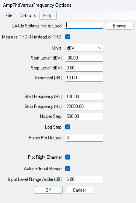
And thus the target input range is the output level + any input gain you specified + system gain. This value is then divided by 6, the ceiling is take of that, it’s converted to int and then mulitplied by 6. And then clamped to 0 to 42 dBV.

I’ll be a bit long-winded here in order to make sure this is correct:

Case 1:
Single ended loopback (sysGain of zero), no input gain specified:

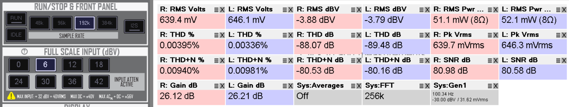
The output gen is set to 0 dBV, and the full scale input is set to 6 dBV. This is correct.

Now set the offset to 12 dBV, and the full scale input is set to 12 dBV. This is correct.

Case 2: Balanced loopback (sysGain of 6 dB) no input gain specified:

The full scale input is set to 18 dBV. This is correct.

Case 3: Balanced loopback (sysGain of 6 dB) and specify 6 dB of input gain. Run the same test as last time:

Full scale input is set to 18 dBV. This is correct, because we have a sysGain of 6 dB, we specified a 12 dB adder and the output level is 0 dBV.

Case 3 (this is a bit closer to what you were seeing, but without the amp). Single ended, no input/output gain specified:

This picks 0 dBV full scale input. This is correct.

And again with -5:

This picks +6 dBV input. Because specified a +6 dB adder, -5 + 6 = 1, and that would round up (due to ceiling).

Is that the same issue you are seeing?

I think the tooltip message could be fixed and improved to take the determined system gain into account. If that is done, what is your preference on how this should operate?

Matt,

Oops, I referenced the wrong incorrectly working test. I have no issues with the AmpThdVersusFrequency test or any other test besides AmpGainAndDistortionVersusAmplitude.

The only test that I am having the AUTOSET issues with is the AmpGainAndDistortionVersusAmplitude test as I showed above. Sorry about that and all the trails you did. If you see my previous post with all the attached graphs, the first graphs are of AmpGainAndDistortionVersusAmplitude and that is where I describe the errors that I see.

I know we have discussed what “Input” and “Output” means. If it was up to me, since you asked, I would reference everything to the DUT. I don’t know if that is how the industry does it or not. Either way is fine as long as it is consistent. Speaking of this, I came across 2 more tests that are weird as far as the input level. They are AmpFreqResponse and AmpFreqResponseChirp. Both of them say “Input Level” instead of “analyzer input level”, but I think it should be “DUT Output Level”. But that is just my opinion.

Another issue I saw over the weekend is the Crosstalk test has a positive dB value. Whereas, everything I see online shows a negative value for the test. The absolute value of the test was correct (as I did it by hand), it is just that it is positive number instead of a negative value. I guess it is just a matter of which channel you are using as a numerator and which one is the denominator in the dB equation.

Dave

Hi, now it is clearer and I was able to replicate the issue. For me it is like this: if you use a DUT of gain G=1 (0 dB) or use a loopback (which is equivalent to the DUT with G= 0 dB) the problem does not occur and the “Full Scale Input” is handled regularly. This was the first test I performed and everything ran smoothly. But later I used a DUT with a gain of G=12 dB and I got the problem reported by DaveD: apparently the “Full Scale Input” is handled very abnormally. It seems to me that the operations performed by the software described by Matt:

are not executed entirely correctly at the software level. It would almost seem that the operation of adding the gain that is added to the output level, which is then used to determine the appropriate “target input range”, is not performed. In fact, if the gain is G=0 dB the amount used to handle the appropriate input level does not change and everything seems to be fine, whereas if G is non-zero, the problems noted occur because “Full scale Input” is underestimated. Of course, this is my opinion and could be completely wrong.

Hi @Claudio and @DaveD, thanks for the excellent reports. Will study more and report back!

Thanks @Claudio for replicating my issues. I think the issue is that the adder is being added to the analyzer output instead of the analyzer input. That’s why a +30 adder works for me whereas I usually use a +6 adder.