Would be nice to see some pics of your system! Your grounding question is a little tricky. The QA403 box is electrically connected to the USB ground. I would try to keep this part floating with respect to your audio ground. It would be easier to find a good solution if you reveal more about your rack, pics would be very helpful…
I would be wary putting the unit in a closed case as the QA403 gets pretty warm with a about 5W of constant heat to get rid of. The vent slots are on the sides.
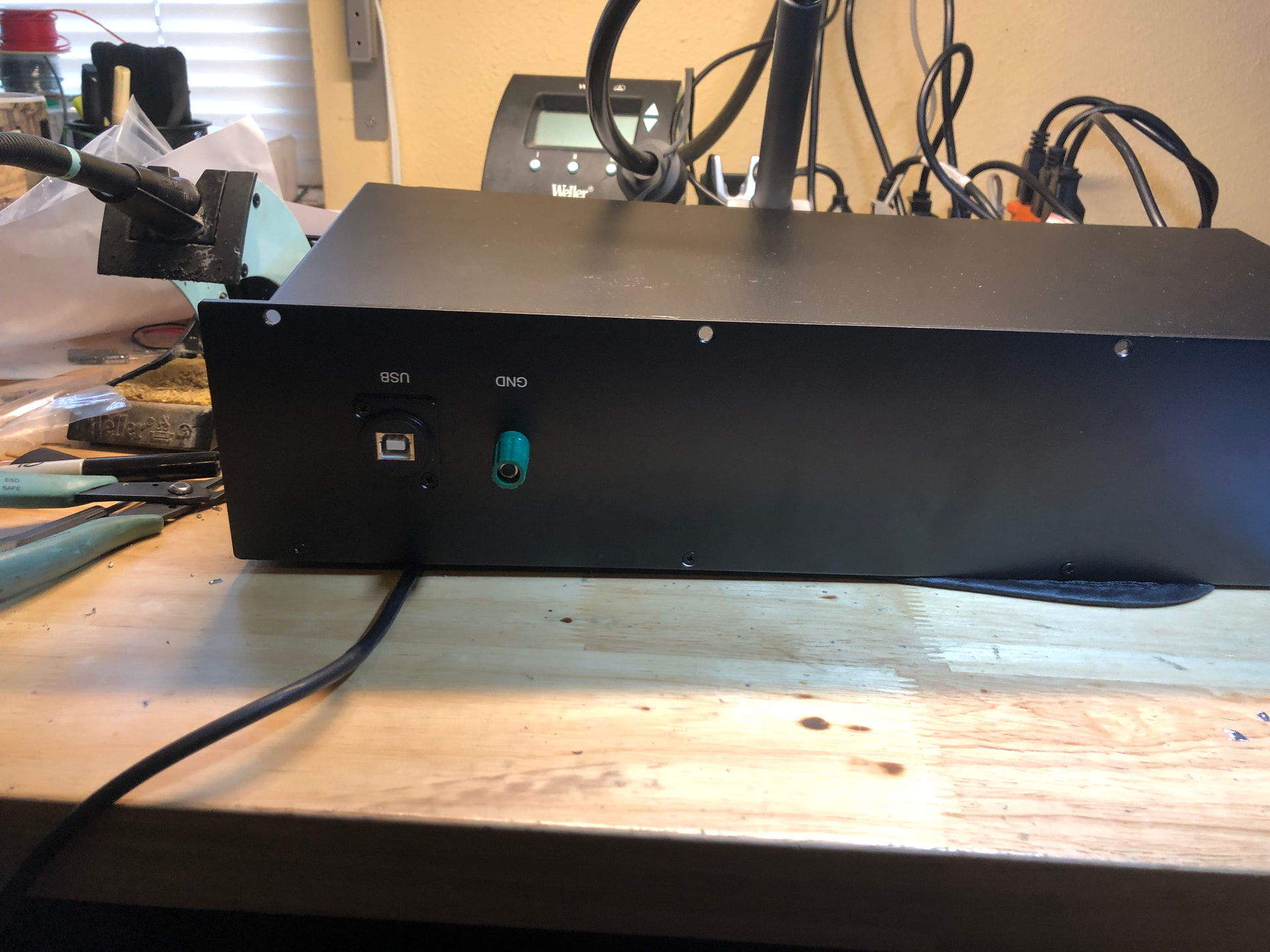
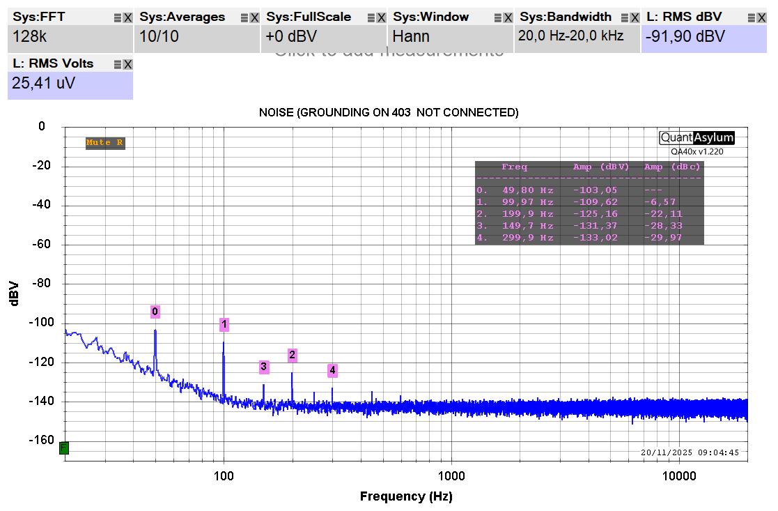
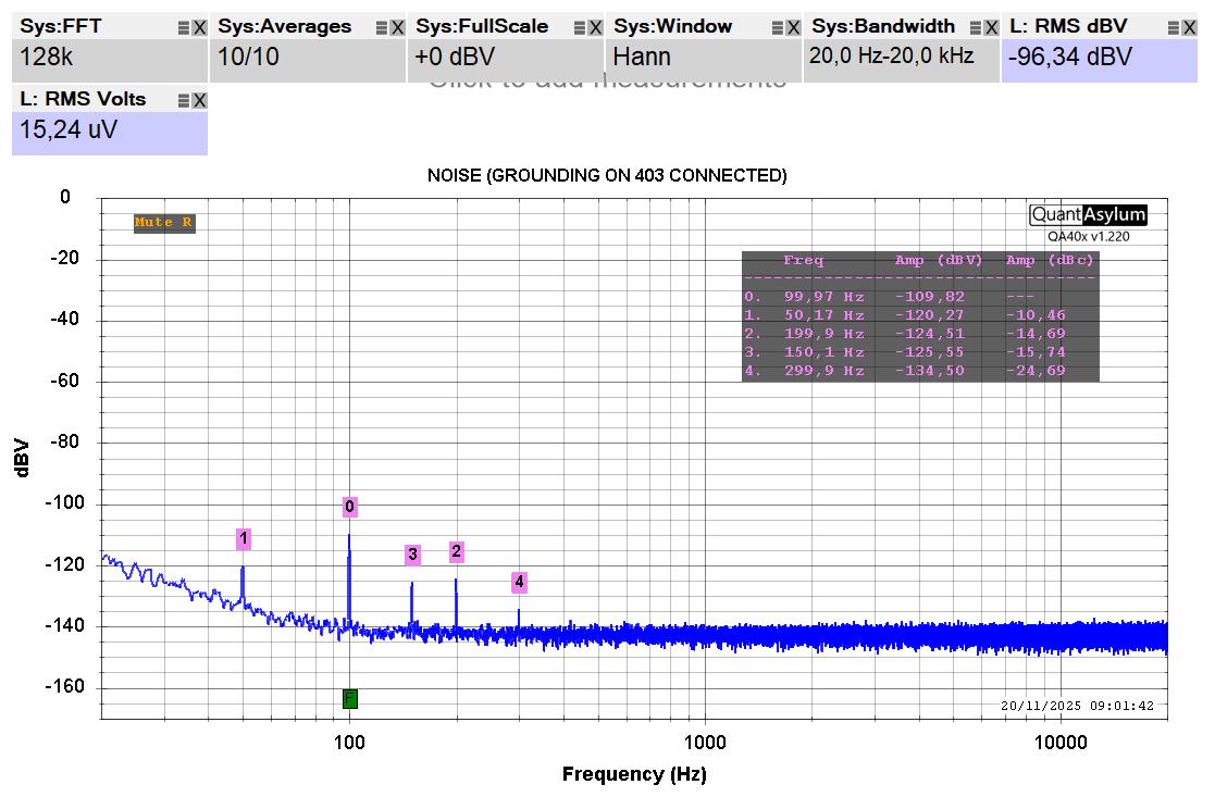
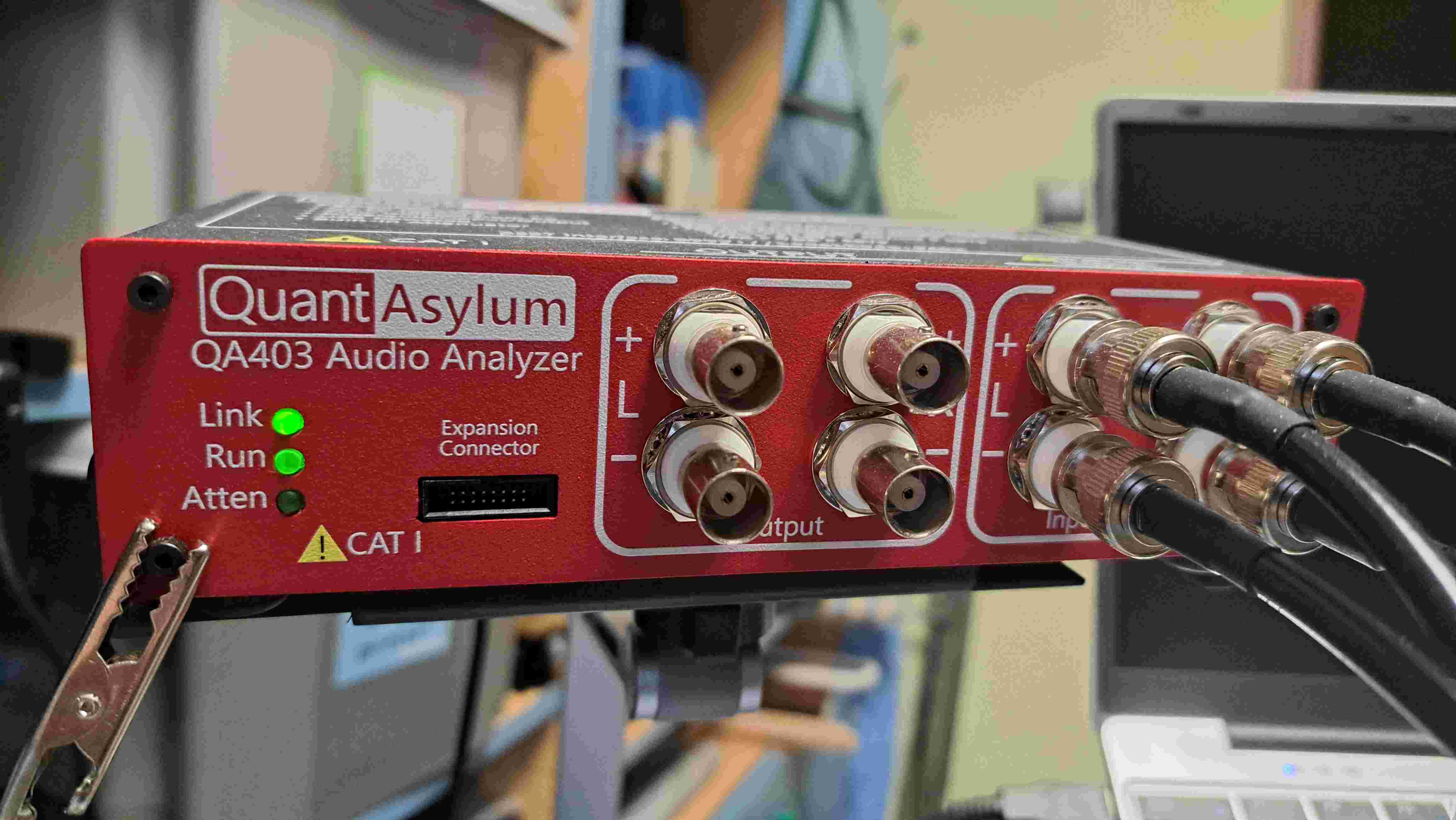
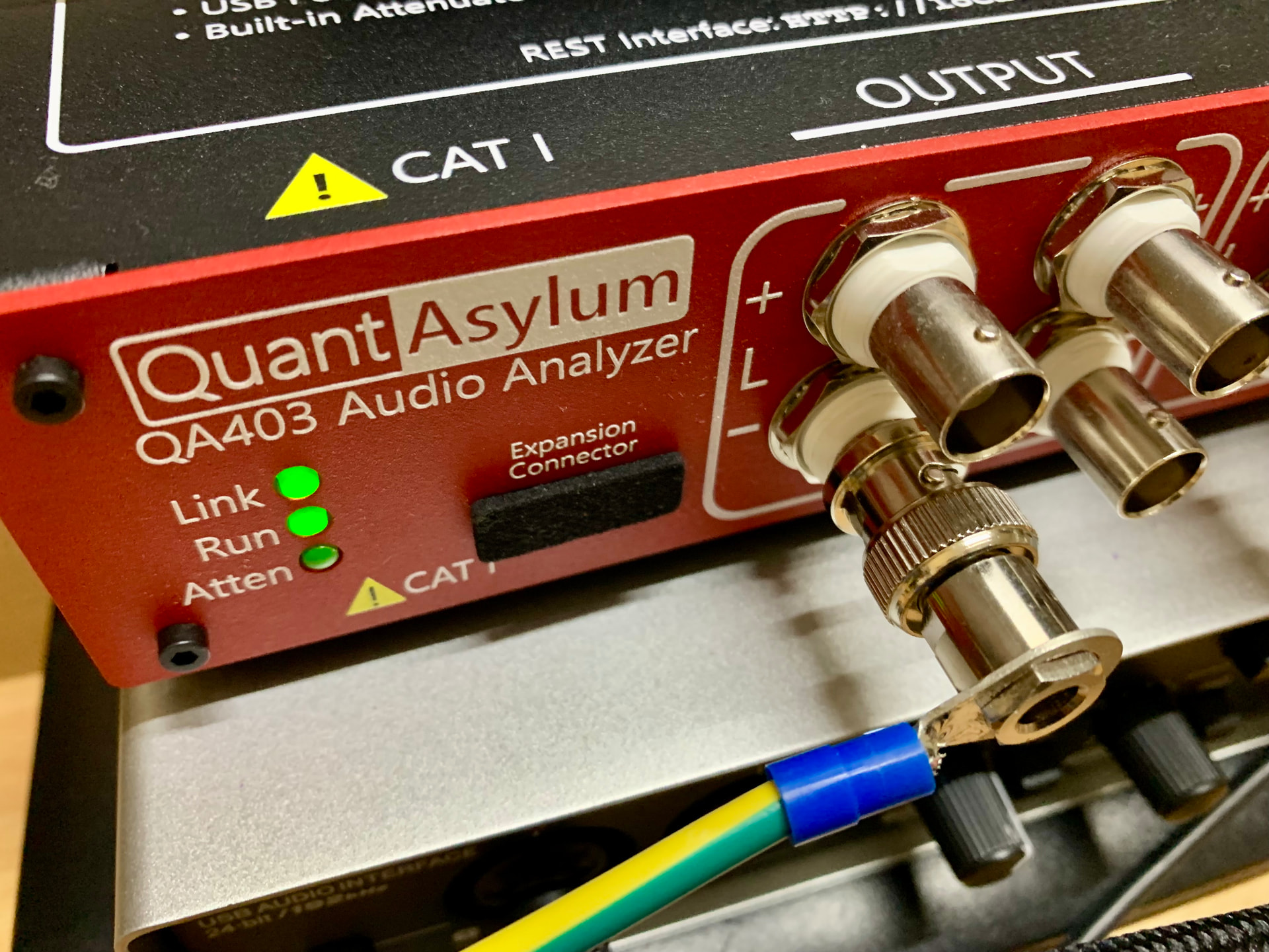
Hi @skipburrows. In the past, I ran some tests with my QA403 to find the grounding point that minimizes the ambient noise introduced. I found that using the bottom left screw on the front panel of the QA403 as the grounding point gave me the best results (after optimizing the grounding paths, of course!). Here is an example of what I get when I connect or disconnect the grounding point. The test was performed by measuring the noise output from an amplifier card. I don’t know if this will be useful to you.
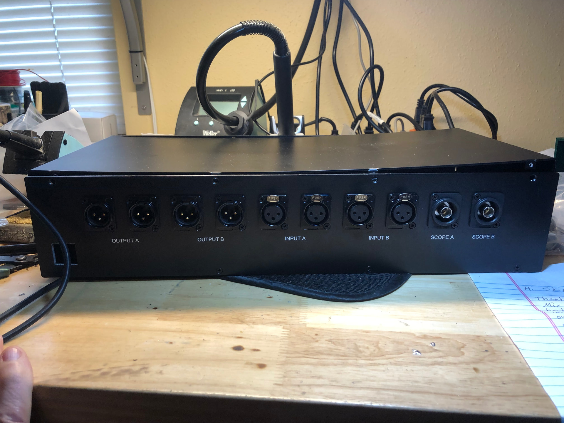
Useful for connecting things extra like headphone amplifiers and even scope to the in our out with the device under test.. better to have it and not need it than need it and not have it!!
I’m skeptical about such an extensive measurement system. Better results are achieved through symmetry, shortening the cables, disconnecting the laptop from the mains during the measurement, etc.
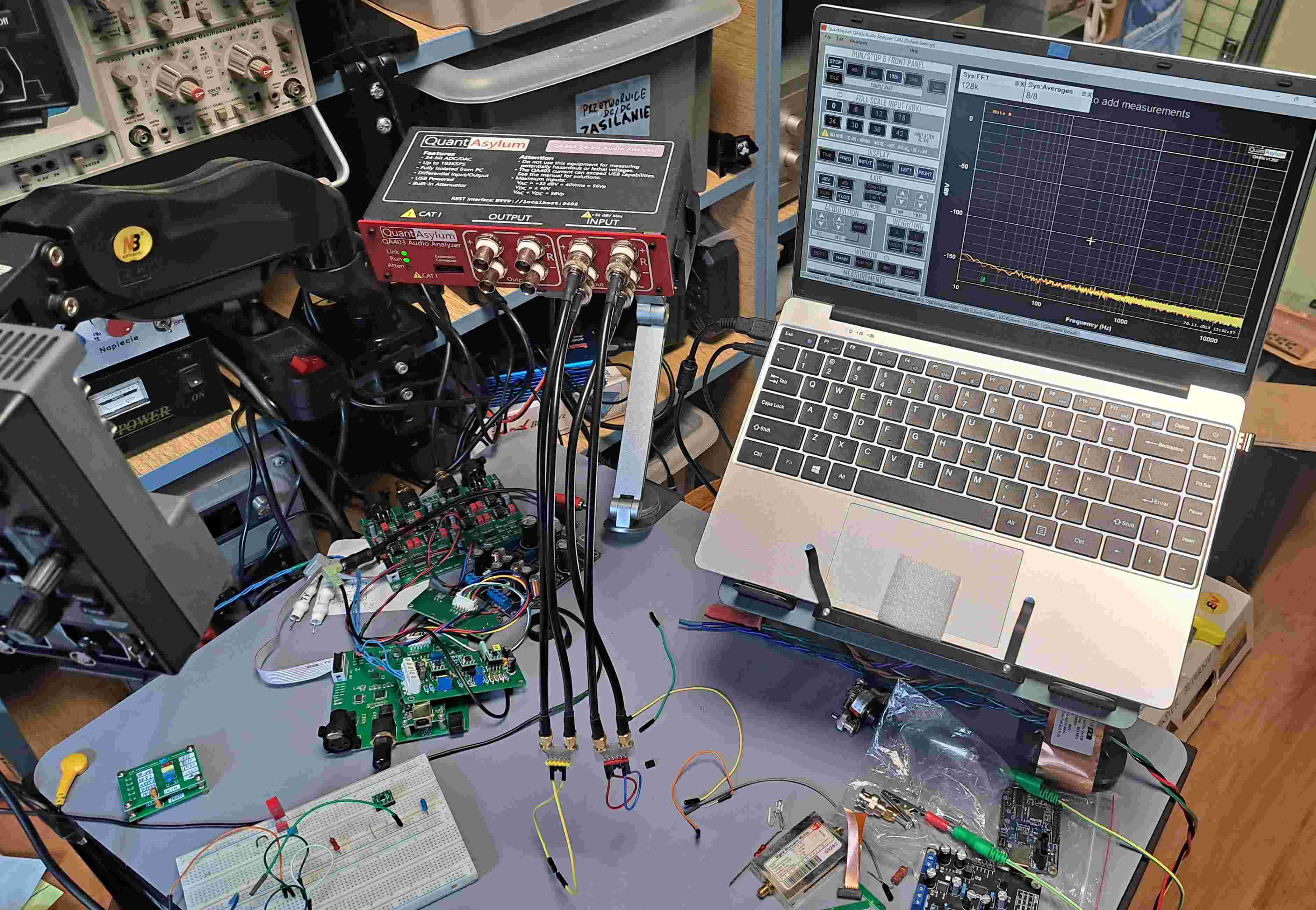
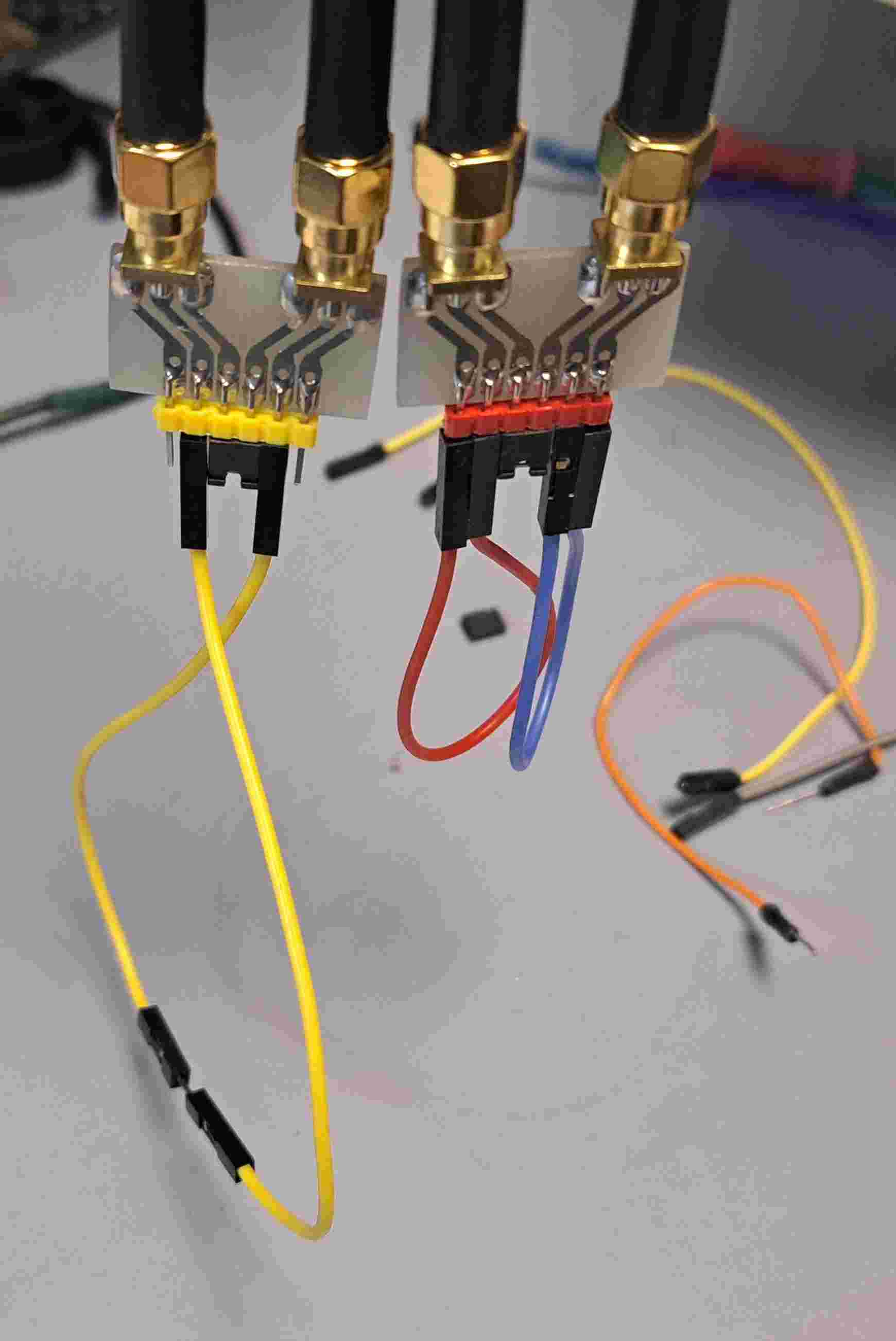
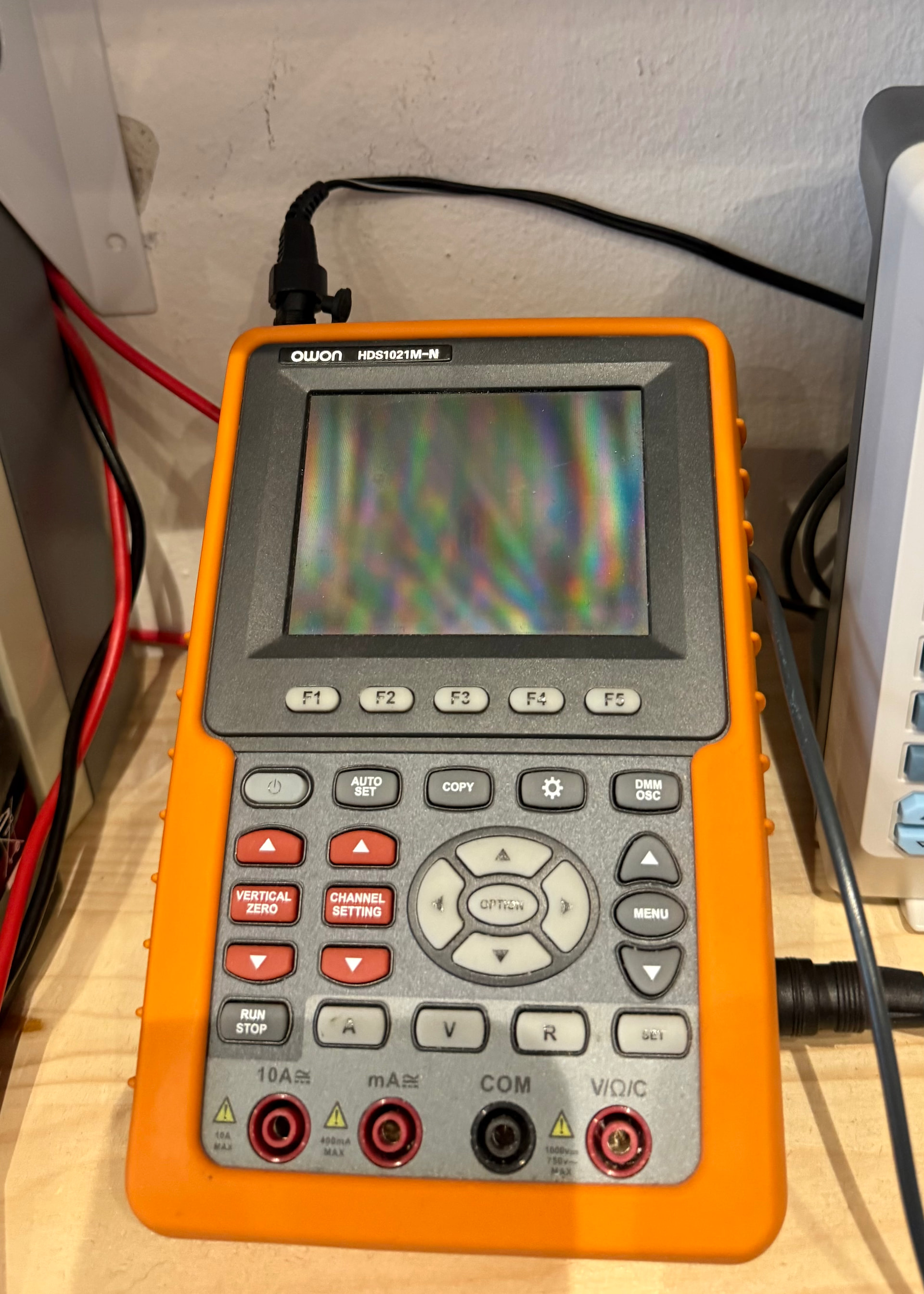
Below is my system. Please note the short and thick measurement cables and terminations (probes).
I ground the DUT by an extra ground wire from a QA403 BNC connector to the PC’s chassis (a HP ProDesk 400 PC). This improves noise suppression, spurious and 50 Hz. residuals a lot.
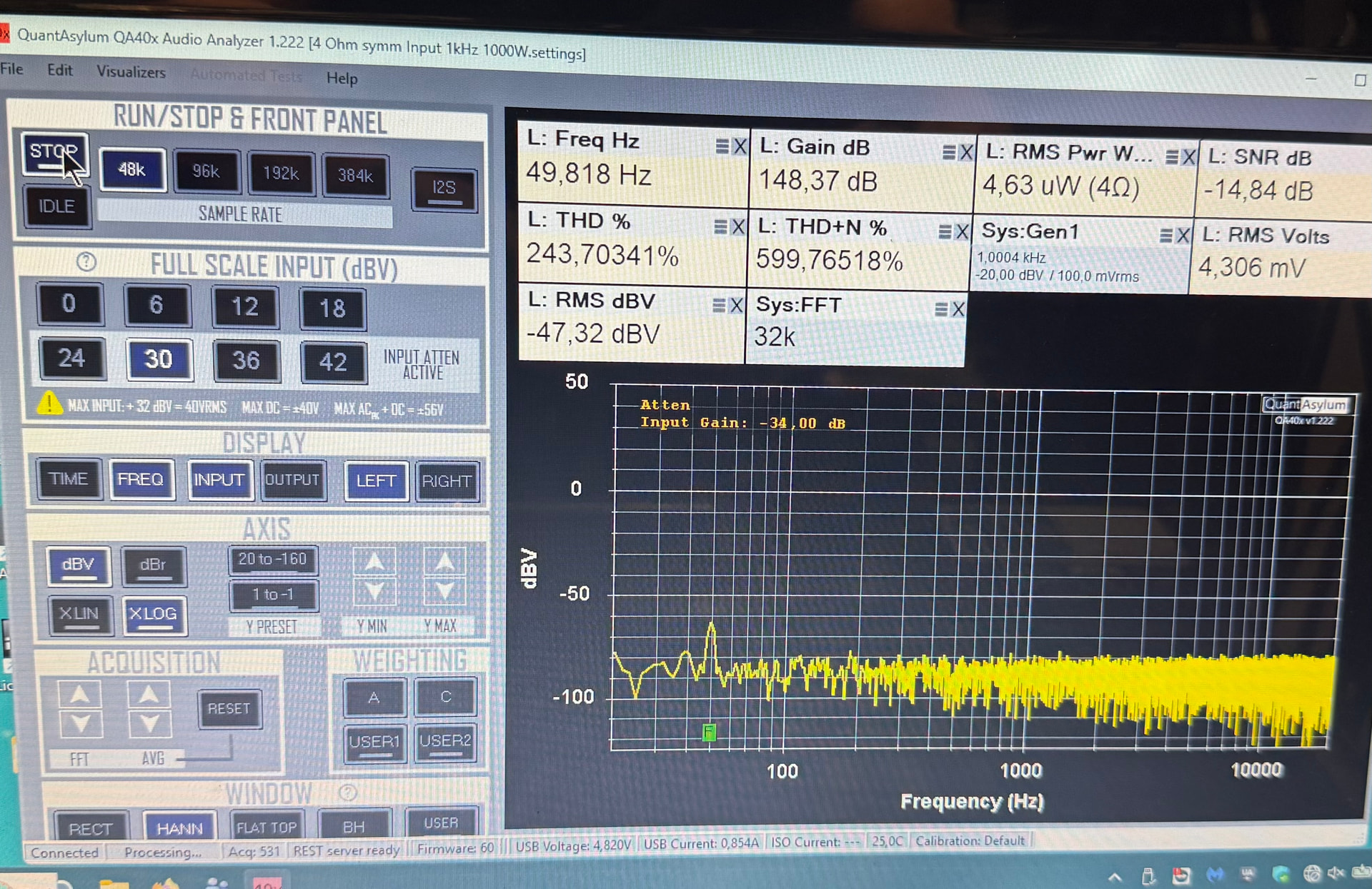
My question is how did you get the extremely low noise floor with measurement settings in the program? My QA403 gives a best of - 120 dB with 512 k FFT size and 10x average. All inputs shorted with 50 Ohm, no cables at all. Or do I have a QA403 which has excess noise level?
Update: My measurement used the internal attenuator. Switched to 0 attenuation I got the -150 dB. Sorry for my question.
Hi Sven.

I was just about to reply.

Exactly as you pointed out: with 42dB attenuators, you'll get about -120dBV, and with a 0dB attenuator, you can even get down to -160dB.

Note my short cables and probes. Everything is symmetrical. You could try a bit with ground shielding, etc.

And the final measurements are done using the laptop's battery, and I sometimes disconnect from the mains to power the DUT with the battery as well.
The attenuator causes the input resistance to be much higher than the 50ohm short would imply. When the setting is 0…18dB the 50ohm short creates an effective 606 ohm resistance on the analyzer input . So the -150dB noise level is from this 606 Ohm resistor. In the 24…42dB attenuation setting the resistance raises 5860 Ohm and that’s where the -120dB noise levels are coming from. If you need lower noise you need to create your own attenuator and use the 0…18dB setting. Had the same learning as you a while ago .
Now I connect my load resistor with built in 40dB symm attenuator, symmetrical connection, chassis of the load is connected to AC ground without ! connection to QA403 ground or housing: