QA451B issue with external loads

I’ve used the QA403 with the QA451B for several years, measuring a wide range of receivers, amplifiers, and amplifier boards including car/mobile audio, home audio, diy, vintage, etc… and have generally found the capability and utility of the equipment to be extremely helpful. Once I gained confidence that my measurements were consistent with other published measurements for the same products, I began to publish some results in public forums, primarily Midwest Audio Club.

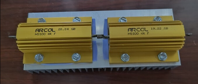
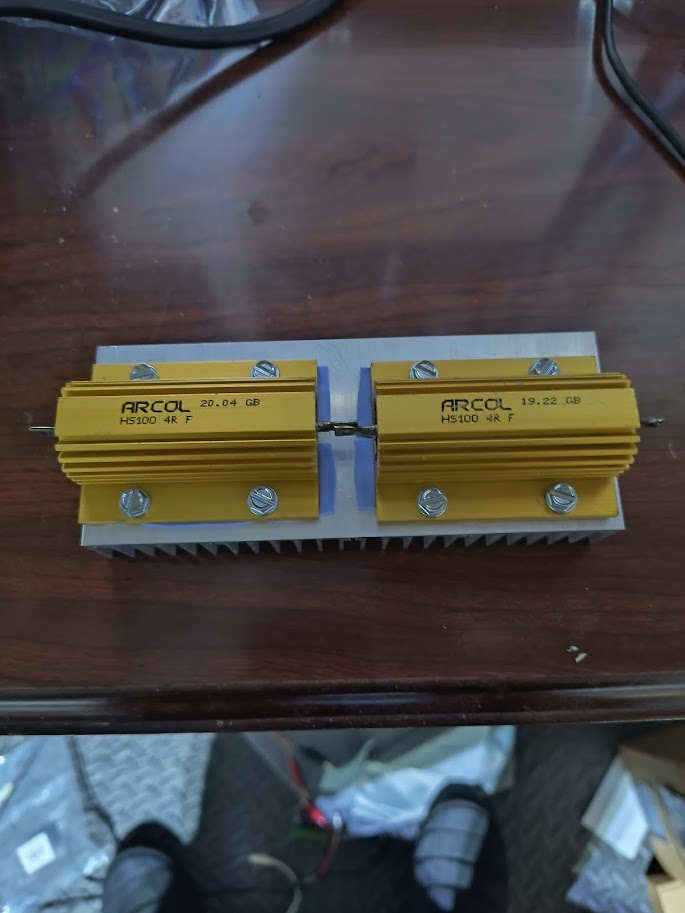
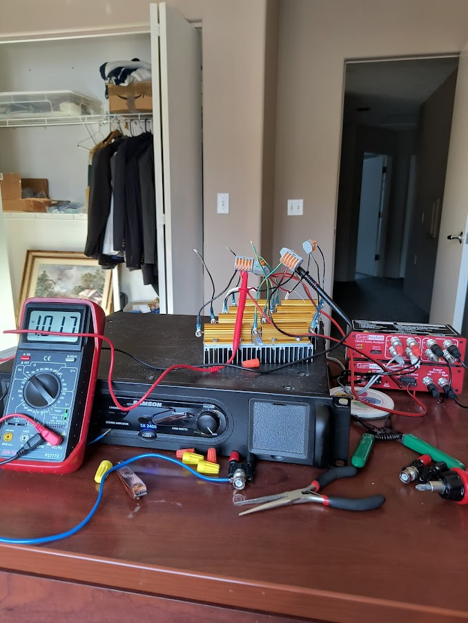
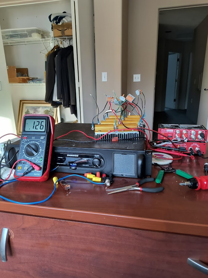
I have always known at some point I would want to test higher power amplifiers than that combo would allow and relied heavily on Matt’s article about using the 451 programmable load with external loads and his subsequent testing of a class D Behringer amp. I built a modular load based on the suggestions in that article. The load consists of 4 ea. 8 ohm “modules”. Each module is 2-100W Arcol HS100 4R f resistors in series. 1 module per channel for 8 ohm testing, 2 modules per channel connected in parallel for 4 ohm testing. I send voltage back to the 451 via the positive terminal on the load and a center tap between the two 4 ohm resistors to get an extra 6dB attenuation (as Matt’s article describes). Here is a picture of a module:

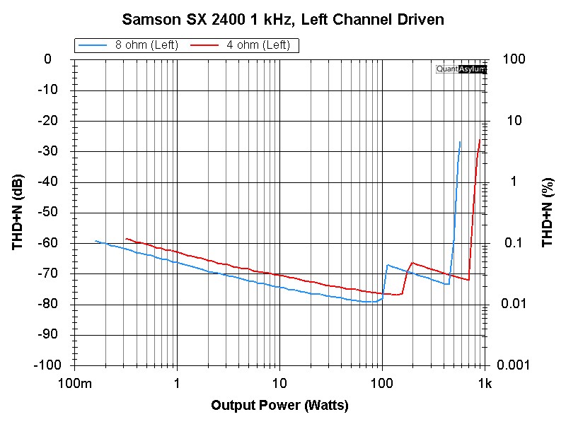
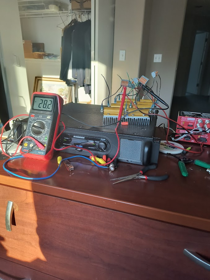
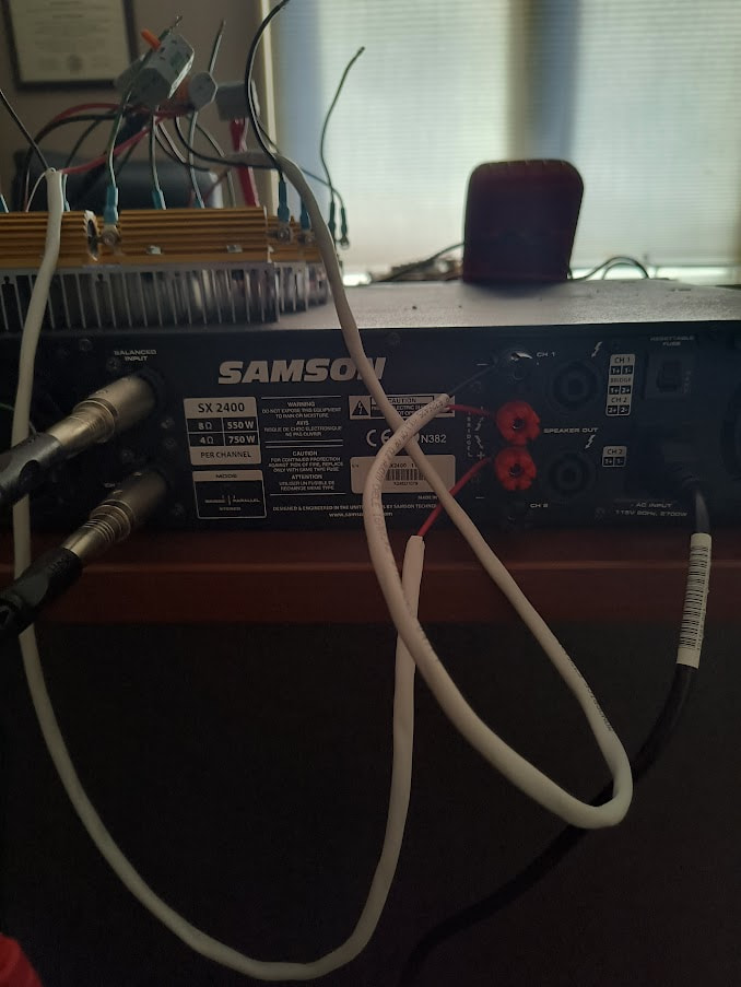
I ran my module array on an Extron XPA1002 plus, which had also been tested by Audio Science Review and got very reasonable agreement with those measurements either using the 451B by itself or with the external load. If anything, the external load measurements looked a little cleaner. Then I hooked up one of my big amps - a Samson SX 2400 rated to produce 550 W/channel into 8 ohms and 750 W/channel into 4 ohms. My initial ASR standard 1 kHz 5W 4ohm testing and frequency response looked reasonable. When I did the THD+N vs. Power sweeps at 1 kHz, I got quite a bit le

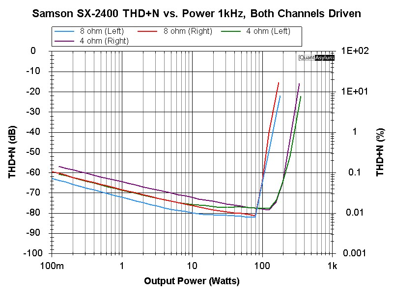
ss output than I expected:

My first thought was that the amplifier was either severely overrated or malfunctioning somehow (it is a class H design, so maybe the power supply wasn’t adjusting the rail voltages correctly). So, I dragged out my QSC CX902, which has similar power ratings and runs one of my subwoofers. I took my first power sweep at 4 ohms.

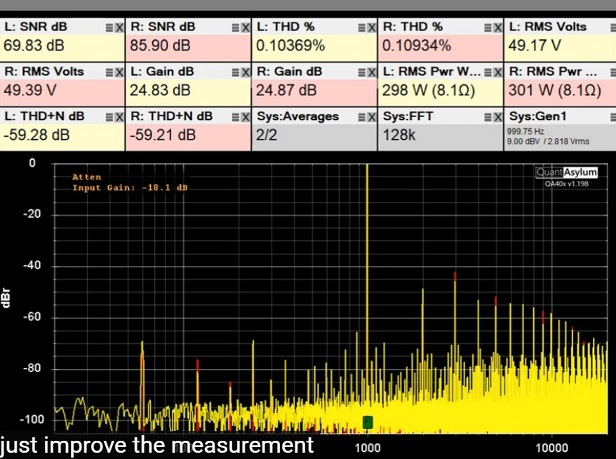
Nope… This looks like an almost identical max power as the Samson and not nearly enough. I went back to the drawing board with my load construction, wiring, settings. Nothing helped. Then, with much trepidation (now running 8 ohm tests so I only have to deal with one load module per channel), I decided to hook up my load (with only 6 dB of built-in attenuation) directly to the QA403. This sweep had to autorange and use the built-in attenuator extensively, so it isn’t as clean.

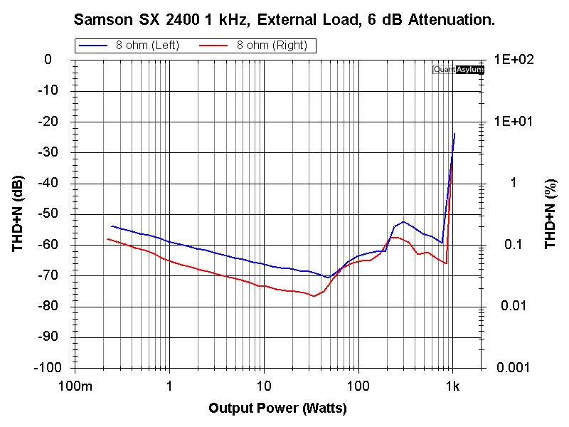
So now we are seeing the expected power output, but I don’t have the 451B low pass filter for class D amps or extra 12 dB of attenuation that would allow cleaner high power measurements.

Any ideas what is going on? I can build a new load with 32 ea. 1 ohm 25W resistors that would let me to get 18 dB attenuation on each channel… But I’m not thrilled to spend the extra funds on that when what I have theoretically should work and I won’t have the class D filter from the 451B, which would be nice for my upcoming IcePower 1200AS2 amp build and test…

I can think of two things that may be causing this.

Is the Samson a BTL/bridge output and have you added the additional 6db to the QA541’s 12dB (18dB total) in the QA software as an offset?

I did run the sweeps with a setting that had input gain of -18 dB. I don’t have a schematic of the Samson amp, but I don’t think it is BTL/bridge output. Per the spec sheet, it is rated for 500 WPC into 8 ohms and 750 WPC into 4 ohms and can be bridged for 1200 W mono into 8 ohms. The amp is described as Class H output circuitry.

I was initially suspicious of the amp, which led me to try the QSC CX902 and achieve very similar results. The CX902 is rated at 550 WPC into 8 ohms, 900 WPC into 4 ohms and 1500 WPC into 2 ohms. It has 2 tier class H topology according to their data sheet. That amp can allegedly put out 3000 W bridged mono into 4 ohms. I don’t see any evidence that the CX902 is a BTL amp.

The QSC CX902 is equivalvent to the DCA3022, which is the next higher model than the DCA2422 that Amir tested. They both claim the same topology.

Hi @Mudjock,

It’s always helpful for me to start testing with just a tone and DVM to make sure everything is working as expected. For example, if I think my amp has 25 dB of gain, set the QA403 to -25 dBV output, connect the amp to the loads, set the QA403 software to a continuous tone via IDLE, and then probe the amp output directly with the DVM assuming balanced (that is, DVM across speaker + and -). And then repeat with DVM to + and ground, and DVM to - and ground. And then measure output of any attenuator. Note all those voltages down, and make sure everything is working as you expect. And then still staying working on a single tone, run a cycle on the QA403 and make sure that reading matches the DVM measurement across the +/- terminals.

Modern class D can have some very strange topologies (and lots of unexpected DC at the output–sometimes half the supply rail), especially as they move to a single rail. And then, you have the issue of balanced and unbalanced attenuators and mixing those with balanced and unbalanced amps. If you use a balanced atten on an unbalanced amp, it will work, but it won’t let you use the input range you might expect. See more at the link below.

Okay Matt - I respect the request for some basic troubleshooting data. Here you go…

I set the Samson SX 2400 to maximum gain, which I confirmed is approximately 42V at the 5W test point I typically use to align with Audio Science Review for comparison purposes.

Next, I set the generator to -42 dBV and turned on the voltage readouts on the graph display.

I also inserted a voltmeter where I make my amp connections across the left channel load.

11 mV difference (about 1% of reading). This looks okay and my meter would not be considered calibrated.

Next, I measured the voltage at the left channel output of the QA451B

There, we are reading 0.126V, which calculates to -17.993 dBV. I believe that is close enough to confirm the basic setup is operating as intended.

For clarity, it is worth noting that neither of the amps mentioned in my original post are class D.

Next step is higher power testing of the same. 100 Watts per channel into 8 ohms.

Here is the same display we did at 5 Watts per channel and 0 dBV:

Based on the power sweep graph from the first post, we are already starting up the steep distortion slope (with increasing power/voltage). The voltmeter across the load agrees reasonably well with that shown on the graph.

Coming out of the 451B, we also get what we expect with -18 dB of attenuation:

Thanks for the data, @Mudjock. Are you sure the amp gain is 42 dB? That’s a lot, and the first spec sheet I can find suggests that 34 dB is expected.

Also, I note in the photo you provided that it looks like your output is hooked up balanced, which means you are delivering to the amp 6 dB more than you think. On the QA403, because there’s not a dedicated BAL and UNBAL port, you have to indicate if you are making a balanced connection via the DBV context menu and the Output Gain textbox. Note there’s a button to preset 6.02 dB, which is what you’d want when making a balanced connection. And once you do that, you’ll see this appear on screen:

That means that when you indicate, say 0 dBV, the actual output will be -6.02 dBV on L+ and on L- (ref to ground aka BNC shell). But if you measure across L+ and L-, you’ll see exactly 0 dBV.

So, in your first picture, your shown output is -13 dBV, but if the connection is balanced then the actual output level is -7 dBV. And so your gain would really be 42-6 = 36 dBV, which makes a bit more sense.

Agree your outputs look as expected.

The 6 dB discrepancy will explain errors with gain calcs. But as you demonstrate, with 100W out (28.32Vrms), your THD is very poor. The SX2400 appears to be able to work in balanced mode, but presumably for this test you are not in balanced mode.

The spec on this amp is 0.03%/-70 dB distortion, and so at 5W with 3H at -80 you are probably close to that. But at 125 mW out you are probably falling short of the spec based on 3H.

Additionally, you have a lot of 60 Hz running through all the measurements, rendering your THD+N not good.

In the 100W measurement, your 2H and 3H are both right at -70 dBc, so your THD is probably around -60 dB = 0.1. You should add a THD tile. But the 2H and 3H are dominating here, so your THDN is probably representative.

Just curious, but what do you expect to see for THD at 100W? Spec says 0.1% at rated power.

Thanks for providing your insight Matt. I wasn’t aware that I needed to set a different output gain when running a balanced output to get an accurate gain measurement. I reran the 100W, 1 kHz test tone with that corrected. I agree the gain makes more sense now.

You are also correct that this amp is capable of running with balanced output (bridged mode).

With regard to my expectations, this is a pro audio class H amp (linear power supply with a big toroid) design more for sustained high power than minimizing distortion. My experience and decades of looking at amplifier measurements suggested that I would have some AC noise (60 Hz plus harmonics) for this type of amp and the 60 Hz noise sitting around -90 dB seems reasonable at 100W per channel. THD I would be expecting to be primarily in the -60 to -80 dB range for this amp. Many times, class H amps will start to produce increased distortion once the rail voltages start to change at higher power levels to prioritize efficiency. The real issue from a distortion perspective isn’t what we see at 100 WPC, but rather what happens as we move up from there. By the time we are a couple of dB up from this, THD is way up to about -20 dB or 10%. I would not expect to see that further increase until at least 600 WPC or so.

Hi @Mudjock, yes, that looks much better! Generator is at -7 dBV, gained by 36 dB of gain to 29 dBV = 28.13 Vrms = 99.29W into 8 ohms. It all makes sense. So now with the single tone working, you can run the sweep you were after before and it should make sense.

Agree on the bnc confusion. If there were more panel space and a higher price point, it’d be better to have XLR out for balanced and a nearby BNC for unbalanced. And when you specify “0 dBV” both the balanced and unbalanced have the same level. But space and cost constraints dictate the shared connectors and so it does require a bit of extra thought when connecting.

Yes, agree on 60 Hz too. Usually, when the supplies start to sag (due to increased current demand) you’ll see the 60 Hz as grass way up in the 1 kHz region and beyond. And sometimes even more pronounced IMD where the 60 Hz products are shown off of each harmonics. Below is a plot from @VAR’s measurement of MC2300 at around 300W and you’ll see the same phenom. And yes, agree, when the grass is ~100 dB below the RMS it won’t be perceived.

PS. What would be cool with the class H is to use the amp dynamics plug-in and see how quickly it can go from, say, 10W listening power to 500W plus. What does it do with a 10mS bump, 50mS, 100mS, etc??

Hi @matt. I completely agree with what you say. However, I think that if in the QA40x software, in the “Generators” section next to the “GEN1” and ‘GEN2’ buttons, there was a small button “Use gen in balanced mode” (or if there were a checkbox in “Signal Generator Setting”) that, when pressed, would automatically set the output gain to +6.02 dB, this would greatly help to avoid misunderstandings and trivial errors due to simple forgetfulness. Of course, this is just a suggestion. Thank you.

Thanks @Claudio, it is a good point.