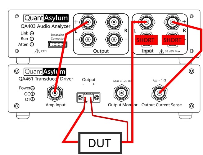
Thanks Dale!
See I can follow a wiring diagram!
Your explanation is what this Autistic guy needs. An explanation as to why! Once I know why I can figure it out!
The truth is as soon as you mentioned current. Ping! Many moons ago I was a rather sharp electronics guy. Now distant fogy memories. But I remember messing up current measurements enough times. Current through the device.
My next question is what gives with the Noise on the measurement? Needs a line filter maybe? It in a common power bar with a computer supply, a monitor supply and an amplifier that has a switching supply as well. There could be plenty of line harmonics.
Master Matt. Maybe fix the diagram in the app note?
Mark
Mark, anything below 4.6V can give problems, as stated in the manual. Since it’s easy to use a powered USB HUB with a short beefy USB cable, I suggest you to make the QA403 at its best. I use this one: Link USB HUB
Mark,
A few averages should clear out the noise. It’s about 4 dB at the highest frequency on both your screenshots. The scaling makes it look so different.
Dale
Thanks Claudio. I am having a little trouble finding this exact one. But you have given me a starting point.
When I bought a powered hub I truly did look for one that had a 45 watt supply. I am going to take a look at the power supply and see what is going on. Just for my own sanity.
I am in the process of finding a comparable hub from D-Link.
Mark
Thanks Dale.
Would you believe that I was a great analog Audio designer in the early 90’s!
Oh what I have lost. When you specialize in a particular field you loose so much in the other ones you were decent at.
I will need to look at how to average. I do this regularly in measuring. Use math functions to remove room echo and get a clean signal.
Mark
In my experience, I found 12V powered Hub to work better with QA403.
I hear you Claudio. It is exactly what I was thinking when I purchased a USB 3 Powered hub. USB 3 should supply 12 to 24 volts. Current is of course subject to the power supply.
So, onboard regulation. I am going to try a different socket and see if there is a positive change.
All the sockets are the same low voltage. I bought a a useless powered USB hub.
So I performed a few experiments over the afternoon. First I used a USB 3 charging adapter from Samsung. It charges at 5, 9 or 12 volts. The voltage stayed under voltage as in my screen shots. I tried the existing adapter with a new 12 volt supply. No voltage change. So I opened up the USB hub just to verify if it really is USB 3.0 compliant. And sure enough on two of the outlets it is set up with 24volt caps and a switching power supply step up converter. Sadly these two ports are not data ports. Only charging ports.
Live and learn. I think that I have found an equivalent for the Link 4 port powered hub. Soon to be ordered.
What has me stymied is that when I plug in the USB 3.0 compliant charger, I do not get a higher voltage. But I believe that is due to there not being a data link to the confuzer.
Not sure if anyone else found this in their travels on YouTube.
Mark
Nice video! THX.
I knew only USB 3.1 type C is capable to supply 12 or 20V. In our use, with QA403, 5V has to be supplied.
What AWG has the cable you use from the HUB to the QA403? And how long is it?
I probably went a little over board with this, but my voltage delivery is now rock steady 5V. Before this I was using a thin cable I’ve had for years and was always in yellow warning range.
I guess any reasonable thick looking cable that promises way more power than you need will be fine. This claims 5A!
I use a Female USB-C to USB-B adaptor (laptop is USB-C only)
Hello Claudio
1 metre 24 gauge.
Hello Dan.
Between you two I am getting a high current supply and a high current cable. I am at a loss how a 12 volt supply I currently have ( measured 12 volts, put a charging load on it via my phone and it charged up quickly via USB 3 section ) cannot properly supply the 403. If memory serves me correctly the USB 3.0 standard allows, 5, 9, 12 and 24 volts. I have not watched the complete video about the innards of the 403, but I am guessing that there is voltage regulation within the 403. Maybe even a step up supply for the op amps.
At any rate, I need this thing to function well. And that it is not doing. This may be a part of the inaccuracy in the measurements of the loudspeaker drivers.
I have a fall back using the Speakertester, but it i son a 12 inch laptop. And I simply don’t have the eyesight to work on that for any length of time.
P.S.
I tried again to load the power supply on my existing powered hub. It is resetting every 2 to 3 seconds. I have a failing power supply. It at least is a reasonably concrete answer to the power problems. With a brief and easy load of a multimeter you will never pic this up.
Round 2.
I found in my multitude of power supplies a 30 watt 12 volt fully approved by all the electrical regulators power brick. Plugged it in and still under voltage. I am guessing it is the 12 volt to 5 volt regulator on the circuit board. I am not interested in this enough to chase it down, plus the size of SMT component is beyond what I wish to trouble myself with. TP-Link 4 port 30 watt supply on it way along with an extra long 30cm cable. (11 13/16")
Proper voltage on the 403
Voltage here is 4.3…
Well I think I cracked this nut with the help of some rather intelligent fellows.
The inductance measurement is considerably different.
Now to do some loudspeaker testing. And see if there is any differences.
Mark
Hi @Kravchenko_Audio, the noise is likely due to the small 0.02 ohm sense resistor used in the QA461. The QA461 can drive up to 1.5A, and for sizable currents a 1A load across the 0.02 ohms will deliver a sizeable 20 mV signal. That then goes through a gain of 50 high-side current sense amp (INA199). This is a zero drift amp with 1% accuracy. The aim here is to provide a simple way to sense current, with a single-ended output.
But, there are limitations. First, there’s the frequency response. The INA199 has bandwidth starts to run out of steam around 60 kHz or so.
Second, the noise is about 25 nV/rthz (RTI). In a 20 kHz bandwidth, this is about 3.5uVrms referenced to input if the noise was flat. So, on the output this would be 175uVrms = -75 dBV. But this is for 1 kHz. Take a look at the INA199 noise density versus frequency:

Note the INA199 noise rises very quickly after 5 kHz or so.
In your plot here, you can see the red trace (current) showing just this. At low frequency the current noise is fine, but at 20 kHz we can see it’s quite high. That’s the INA199

So, I think the takeaway is this: If you see the current trace showing fuzz at higher frequencies, then it will result in fuzz on the impedance plot.
Next, think about the currents being measured. In your case, you are driving at -40 dBV = 10mV. And that 10 mV drive is resulting in a 10mV/10 ohm = 1mA current. And in the 0.02 ohm sense resistor, that is resulting in a 20uA current, which is pretty small. If you used a 10 ohm series sense resistor (and a diff measurement into right channel across the 10 ohm sense resistor) and bypassed the internal current sense on the QA461, you’d see the noise and bandwidth improve considerably.
The QA461 current sense will work well for sensing higher currents–from 10’s of mA to 1.5A. But as currents drop below 10 mA, the circuit limitations will start to become apparent. When the QA461 first came out, component testing wasn’t a priority. I think a subsequent QA461 will want a few switchable sense resistors–maybe something like:
| Sense R | Range |
|---|---|
| 0.02 Ohms | 1.5A to 50mA |
| 0.2 Ohms | 150mA to 5 mA |
| 2 ohms | 15mA to 500uA |
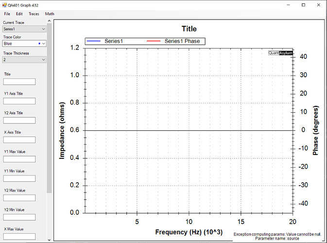
Seems like the Impedance calculation is not working. I have not changed my previously functioning connections between the 401, and the 403 or to the device under test. Again I have some drivers coming in that I designed and need to verify. And again I am hoping to be able to compare the results to my old standby to see if the QA software is indeed closer to proper loudspeaker measurement.
Clean install. Old version removed via windows App manager. QA latest installed and test tried out.
I get the following screens:
Not sure what is going on.
Mark
Hey,
I can’t help too much, it seems an internal error in the software that will only make sense to Matt: QARemotingException. But I’d try changing a few settings to see if I could avoid the error. The smoothing settings seem quite extreme, I normally don’t use any smoothing because I want to see the raw data.
Cheers,
Dan
Hi Dan
Referring to smoothing. This is the pre-canned settings. Normal smoothing for high resolution measurements is 1/48th octave. This is set at 1/96th octave. Much finer than realistically useable.
I am seeing teething pains with the QA products. And still I’m using my good old standby. I guess there are not so many people that are using this for loudspeaker development. A pity as this should be a world class type system. I’m holding out for some accurate and stable measurements.
Mark
It’s interesting what you are doing - so you just want the impedance or is it the speaker parameter stuff that is not working?
Yes impedance and the T/S parameters.
Neither are working. I’m running software version 1.926.
I design and test drivers for different companies all over the world. Some pro, some Hifi.
I have a solid system that requires a long in the tooth windoz 7 machine to use it.
Making me wonder what fun and games I will have if I buy the microphone amplifier. Teething pains I am hoping.
Better things to follow is what I expect.
Mark
I would debug this by looking at the signals you get for your voltage measurement and your current measurement. And I would do it for a simple resistor. Then I’d manually perform the impedance calculation. Nothing stands out to me from the screenshots. So it’s a case of step by step debugging. Anyway that’s what I would do.


