OK like i promis, i did an TS Measurment on an oder Audax HM170Z18 Midwoofer.
I used that 27,22 OHM (Measured with SDM3065X with 4 Wire probe) Senseresistor from Artabox nothing else from it.
Also RDc measured with 4 wire Probe = 6,05Ohm
I used -37,5 dBV and got 100mV rms on the Speaker like sugested on Arta Limp Datasheet.
Impedancemeasurment looks this way realy smooth:
My measuring scale was measuring 100,25g when i used an referense wight of 100g.
so i measured 4 Magnets at 18,97g and decidet to use 18,93g
But the Magnets give me some new resonances on the Impedance so i guess i use again
Playdough in the Future or other flat Magnets need to test it.
I didn’t know how to provide an File here so i made an Picture of the TS Parameter:
The QMs and VAS is far away from Datasheet 7,5 instead of 4,07 and 2,562Liter instead of 35,39Liter but it was not Burned in, so may be i need to let them play some hour with 40Hz or so.
And here the Datasheet:
SO i am realy off with my Parameter but this Speaker i have already 15 Years or so and never used them, in orig. Package 
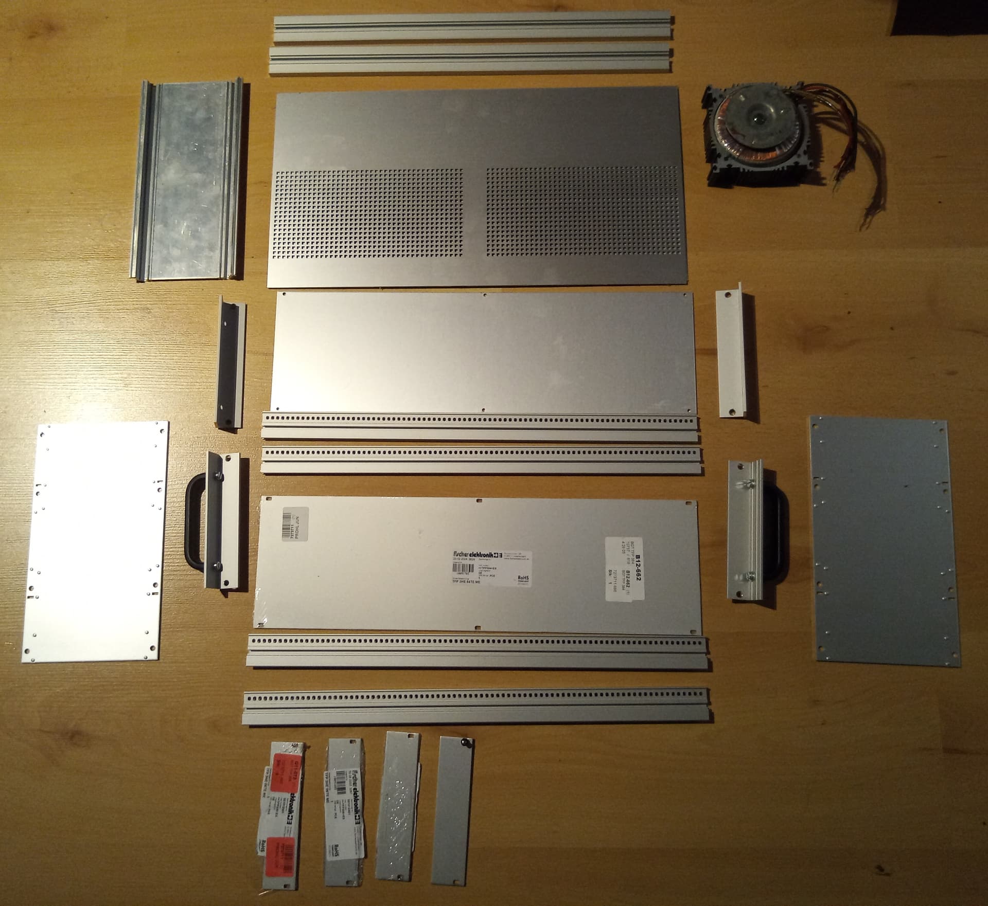
My Chaos Setup, i also need to Measure all the Wireresistances i guess.
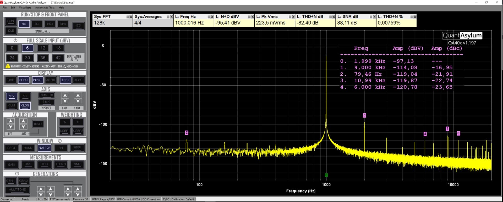
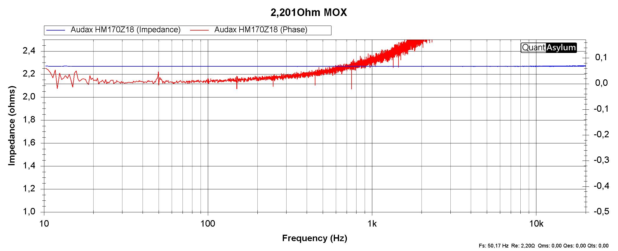
I measured an 2.201Ohm MOX Resistor and got a Line around 2.4 Ohm on QA403
So next day i will do some Wirecompensations and do the same again
Also with REW
Now i used my old methode with Playdough (The Magic is to put the weigh close to the Voicecoil! But with Magnets i dont want to do it, because of the influence to Magnetic field of the Voicecoil) :
Less Weight also, only 7,26g
Much better!
But the VAS is still far Off 
Wire Calibration was helping a bit, here the Measured 2,201Ohm MOX Resistor:
@ 2,26 Ohm i would say
RSense with Wire is now 27,298 Ohm before 27,22 Ohm.
TS Measuring now:
and the Data:
Stil VAS is far off!
Simulation with orig Data from Datasheet:
Volume 25L looks good.
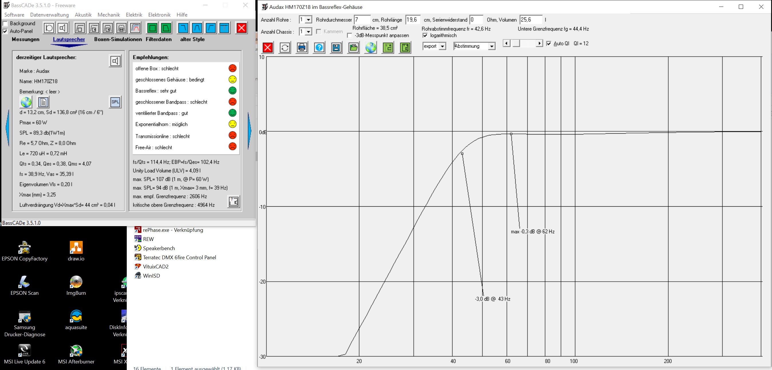
And with the Measured TS Parameter
Volume 2,8 Liter and an Bassreflex Tube 170cm long thats absolutly crap something is wrong with the VAS Value Calculation
Also the Inductance is more than twice high instead of the orig. Datasheet.
I guess because of all the used Wire.
Need to rethink this Setup, all Wire need to be short as possible i guess.
May be the Rsense Resistor is to high need to try an 1 Ohm 5Watt next day or anything like this.
Or i do something totaly wrong.
Next day i try another speaker that i bought this Year, let see
And of course using REW and may be ARTA for Comparing.
Last for today with Rsense 2,2Ohm and short wire to Rsense, but not much difference.
Again 100mV RMS at Speaker (@-47,5dBV)
OK Guys cant believe this but the Problem is the Speaker absolutly to old, i guess i can throw them away …
Measured now my new bought ScanSpeak 18W/8434G00 with the same Setup and Weight!
And here the Datasheet:
FS=50Hz (54,7Hz QA403)
RE=5,6Ohm(5,54 SDM3065X)
Qts=0,43 (0,49 QA403)
Qes=0,46 (0,54 QA403)
Qms=7,58 (4,86 QA403)
VAS=19,5L (18,897L QA403)
Le=0,55mH (0,727mH QA403)
BI=7,2Tm (6,41Tm QA403)
So for an not Burnt in Speaker not far from Datasheet
Simulation with Datasheet Parameter:
Simulation with Measured TS Parameter:
Next day i will Burn it in and measure again , let see how it will Change
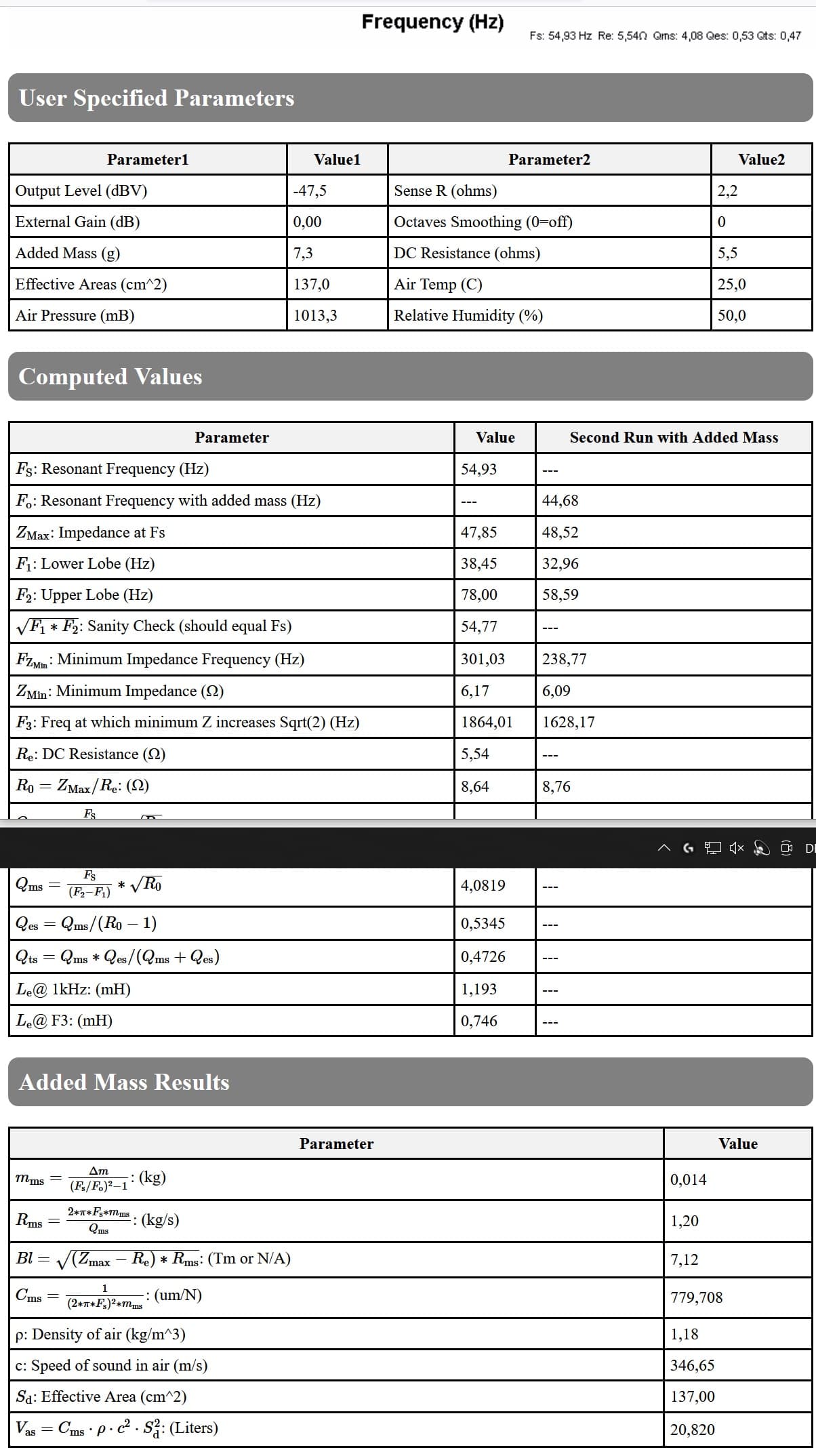
Did an 3 hour Burn In prucedur with 30Hz and around 6mm p-p Cone Movement.
FS=50Hz (54,7Hz QA403) (54,93Hz BurnIn)
RE=5,6Ohm(5,54 SDM3065X)
Qts=0,43 (0,49 QA403) (0,47 BurnIn)
Qes=0,46 (0,54 QA403) (0,53 BurnIn)
Qms=7,58 (4,86 QA403) (4,08 BurnIn)
VAS=19,5L (18,897L QA403) (20,82L BurnIn)
Le=0,55mH (0,727mH QA403) (0,746mH BurnIn)
BI=7,2Tm (6,41Tm QA403) (7,12Tm BurnIn)
So an smal change in Values but nothing much different on Simulation.
May be 3 Hour isn’t enough.
Some say its enough for an hour some say at least 24hour needet i am not sure may be an Expert could say something abaut that Burn In Time.
Stil Simulation say 7 Liter more (35,6L for 42Hz -3dB) than the Datasheet says (29L for 42Hz -3dB)
Anyway i bought 4 of them for an MTM Configuration in a closed Box, and use of 2 Ripole Subwoofer’s with 2 12" Chassis in each Subwoofer
So i will use 15Liter for one Cassis in a closed Box.
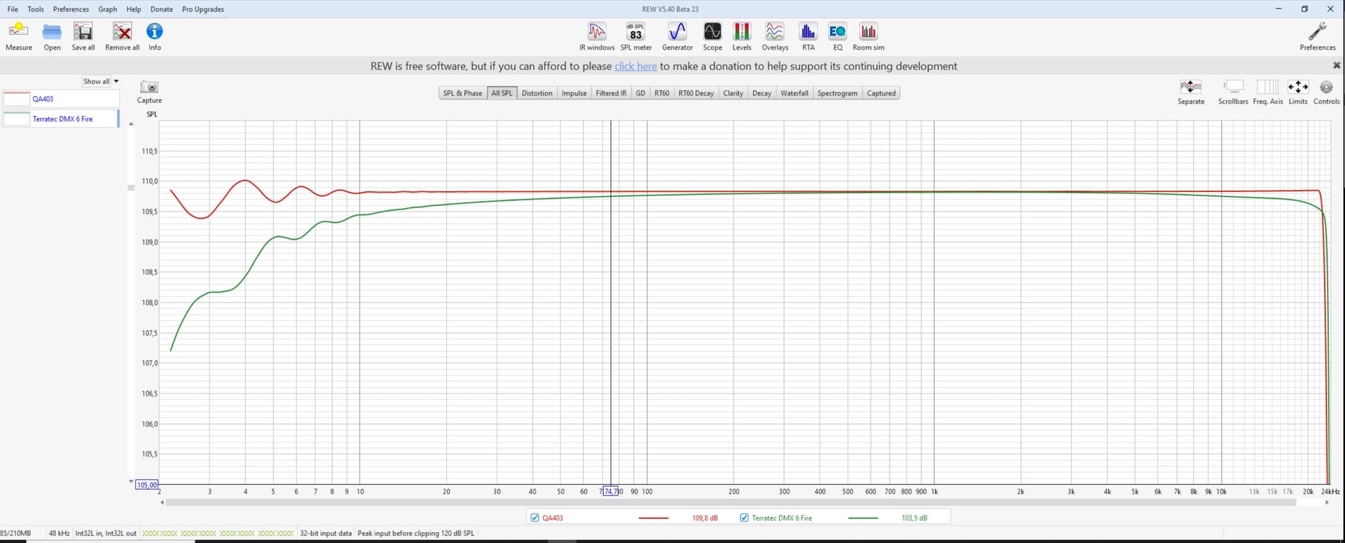
Same procedure this day with REW using this Connection and an 100Ohm (99,82Ohm) Rsense without an Amp:
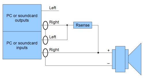
One Qote here to say: on that QA403 both Inputs Single Endet at + Connection has an Phasshift of 180 degre!! so this measuring was’nt working until i go to left IN “+” and Right In “-”
Measured Resistor 2,20 Ohm MOX after Calibration:
Speaker Measuring:
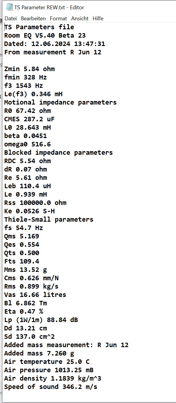
Calculatet Data:
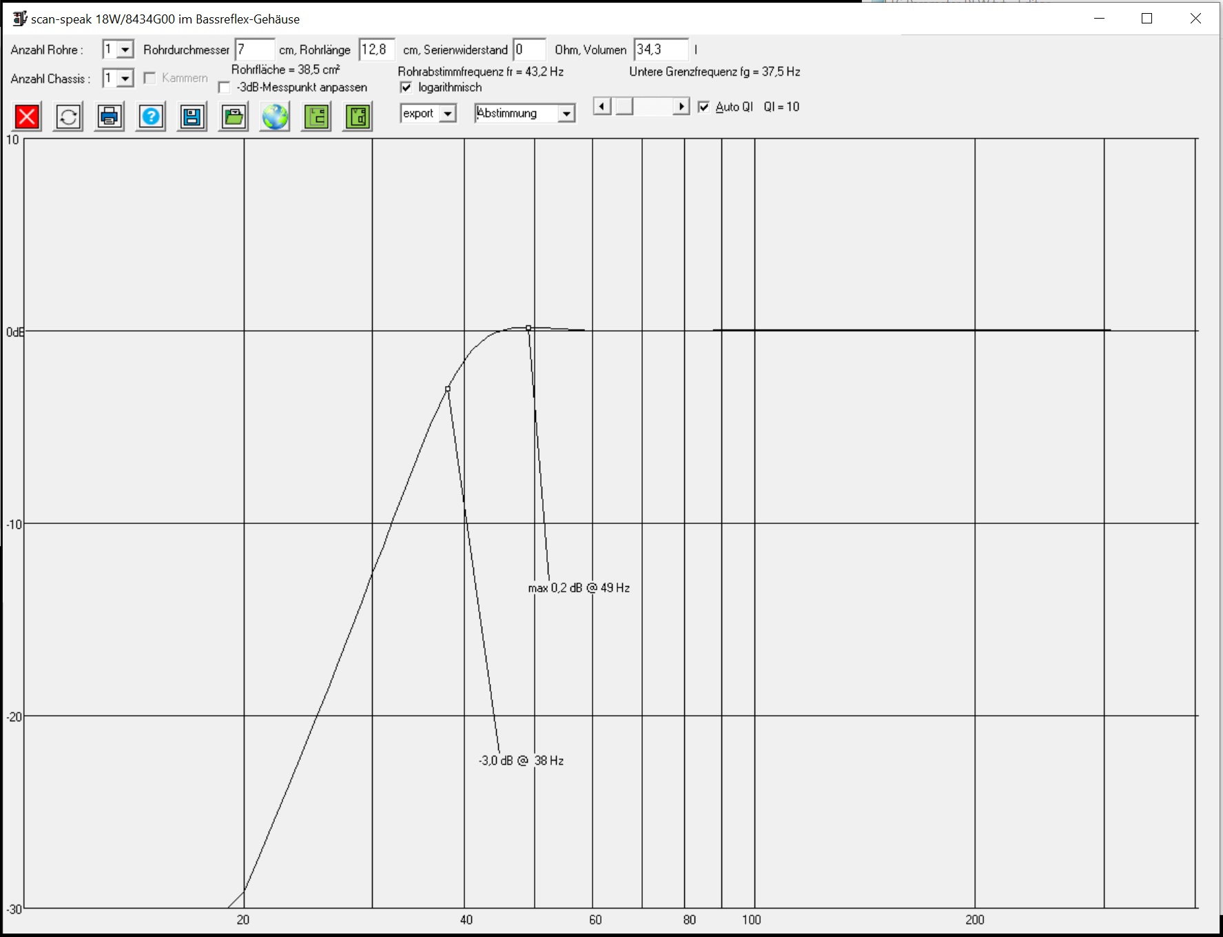
and here the Simulation:
Not much change in Volume for Bassreflex but 38Hz @ -3dB instead of 42Hz
FS=(
54,7Hz QA403) (
54,7Hz REW)
RE=(
5,54 SDM3065X)
Qts=(
0,49 QA403) (
0,5 REW)
Qes=(
0,54 QA403) (
0.554 REW)
Qms=(
4,86 QA403) (
5.169 REW)
VAS=(
18,897L QA403) (
16.66L REW)
Le=(
0,727mH QA403) (
0.346mH REW)
BI=(
6,41Tm QA403) (
6.862Tm REW)
Is there an Calibration option for the Impedance Measuring on QA403???
The Resistor 2,20Ohm was a bit off (2,26Ohm) there without Cal. \o/
REW was 100% Spot on with QA403
Robert