With any quality loudspeaker the change in the driver after running should be very little. As you have shown, there will not be enough change to affect the box design in any way. The days of needing to break in a driver are 20 years and more ago, or with very inexpensive drivers.
BTW i got an Massage from UPS some Devices are on the way from Saelig!
Let see what i get next Day from the ordered Devices (Order QA472, QA451B, QA461 (462) still open)
I guess the first Both
Have this Attenuator lying around with 10KOhm in Stereo and 24 Stepps.
Need to measure it but i guess it has -3,2dB per Stepp.
So i could use it also Differential up too -73dB Log
Every stepp only one resistor in serie, one Parallel.
Probably this one: but my is already more than 15 Years old and now time to use it
One newbe question:
Why the Noise Numbers didn’t show as negative Numbers ? Like THD.
Means it:
Signal is @ -20dB, Noise is 81,87dB away from it? and not @ -81,87dB right?
I guess for better Noise Measurings would be good to add after the Attenuator an descend Amplifier to get the Signal back to 0dBV right? -20dB Atten. then +20dB gain Amp and so on right?
Also no intefearence with Input Impedance i guess.
I can do it next days, got already the Cosmos APU.
It has an decsend Amplifier in it +34dB and +60dB
But i ordered Cabeladapters, i hope i get them next day from Amazon
And Pssst QA472 and QA451B is incomming @ Monday AM.
Than i could do some Tests with my Class D Hypex Amps NC122MP and NC250MP.
Hi. “SNR” Tile is not the noise but the signal-to-noise ratio. If you want to display the noise, you have to select the “N-D dBV” tile, and you will see that if you select it, the noise will be expressed by a negative dB number.
Yes. But it is actually the measurement of only the noise in the analyzed signal, while the “N+D” tile measures the noise component plus the distortion component of the analyzed signal.
Hello,
Replaced the Mesurings for N-D and looks much better
But at the End it gives the same SNR Numbers:
-105db N-D +20dB Gain =85dB SNR
-114dB N-D +40dB Gain = 74dB SNR
-118dB N-D +60dB Gain = 58dB SNR
Right ?
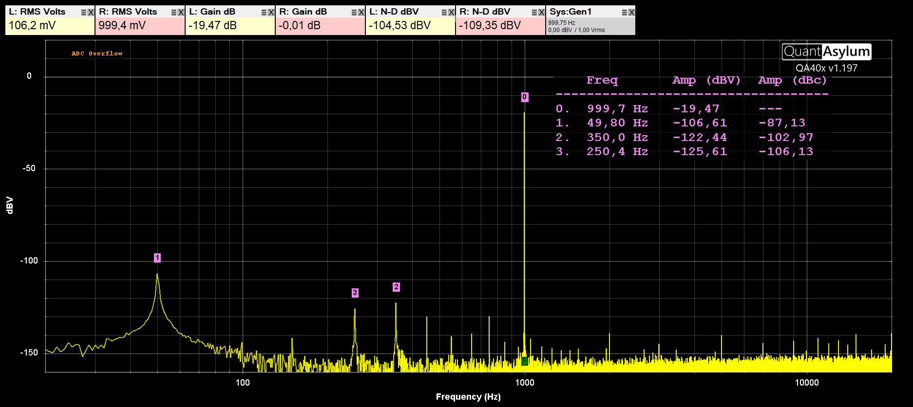
The 50Hz Spike is a bit worse, may be Shielded Wire would Help.
This 50 Hz Spike happen every time i didn’t measure Differential!
I guess it cals Comman Mode Error or so right?
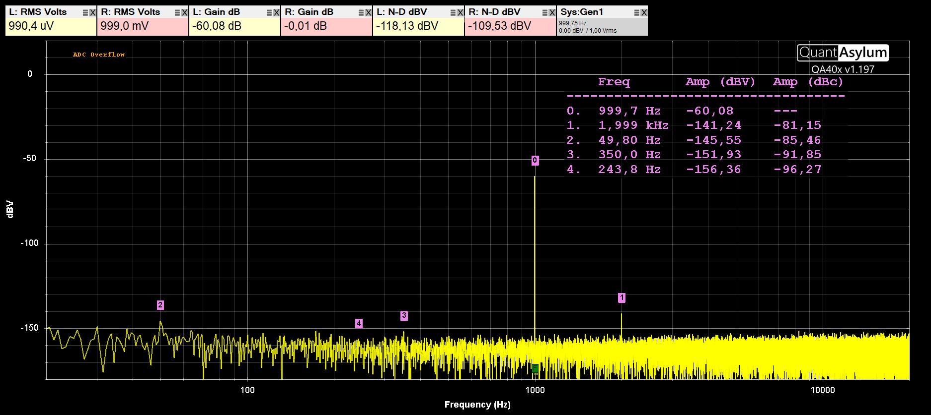
Tested my Cosmos APU and if i measure it Single Ended i get this Spike @ 50 Hz and if i use Differential input i didn’t see it.
Like Here:
Hi Frunse. Of course they must be the same numbers! SNR= 20log(S/N) which by the properties of logarithms (using the expressions of the various terms in dB) becomes: SNR = S - N. From which:
N= S - SNR, where N corresponds to N-D.
Hi, at this link you will find useful information on minimizing induced noise in measurements made with the QA40x.
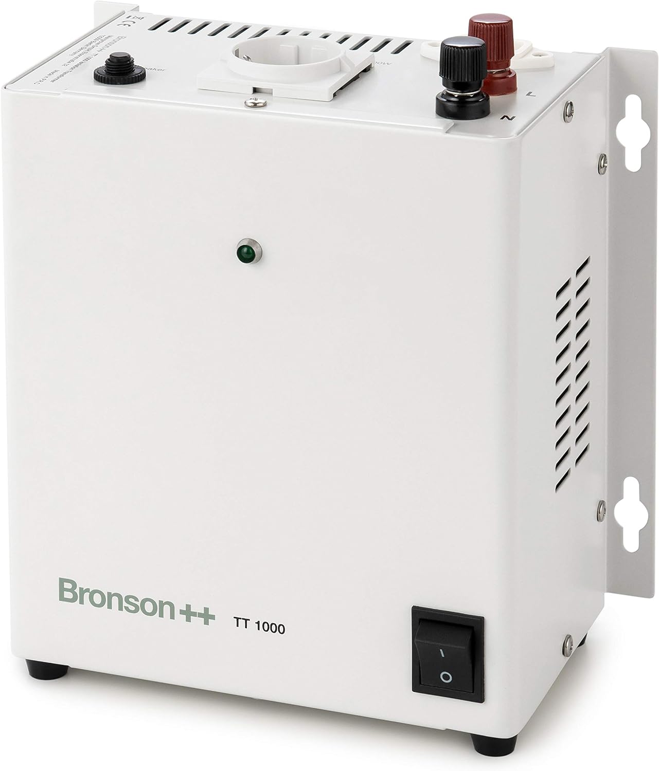
An isolation transformer will hardly solve these problems, since there are many different ways to introduce these disturbances (radiated mode and conducted mode, capacitive coupling and inductive coupling, etc.). In any case, the one in the figure is not an isolation transformer, but a VARIAC that does anything but isolate.
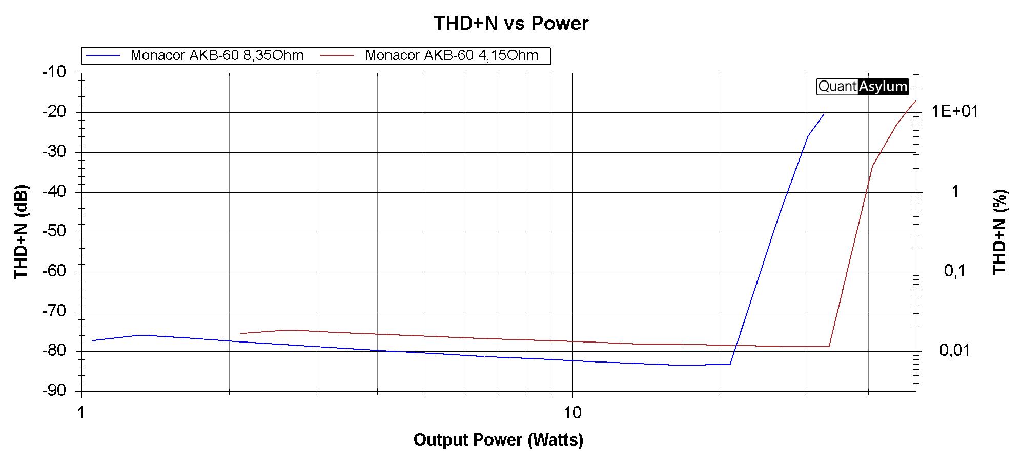
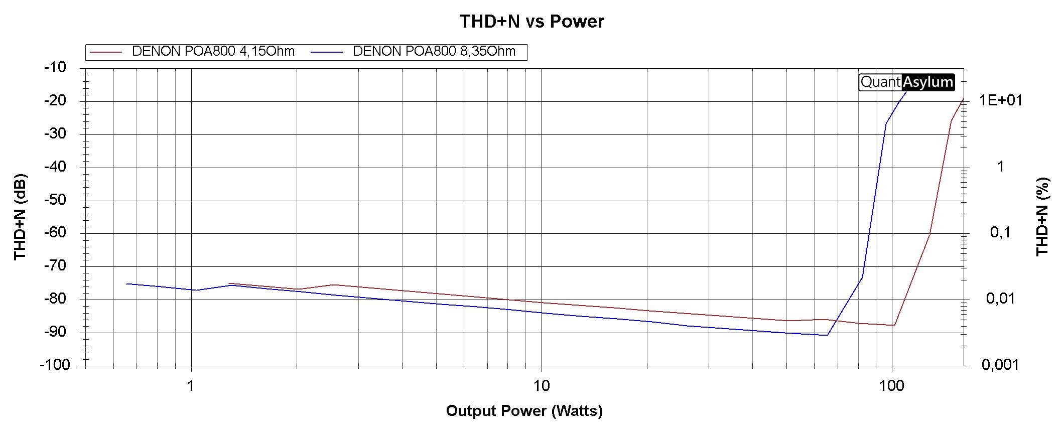
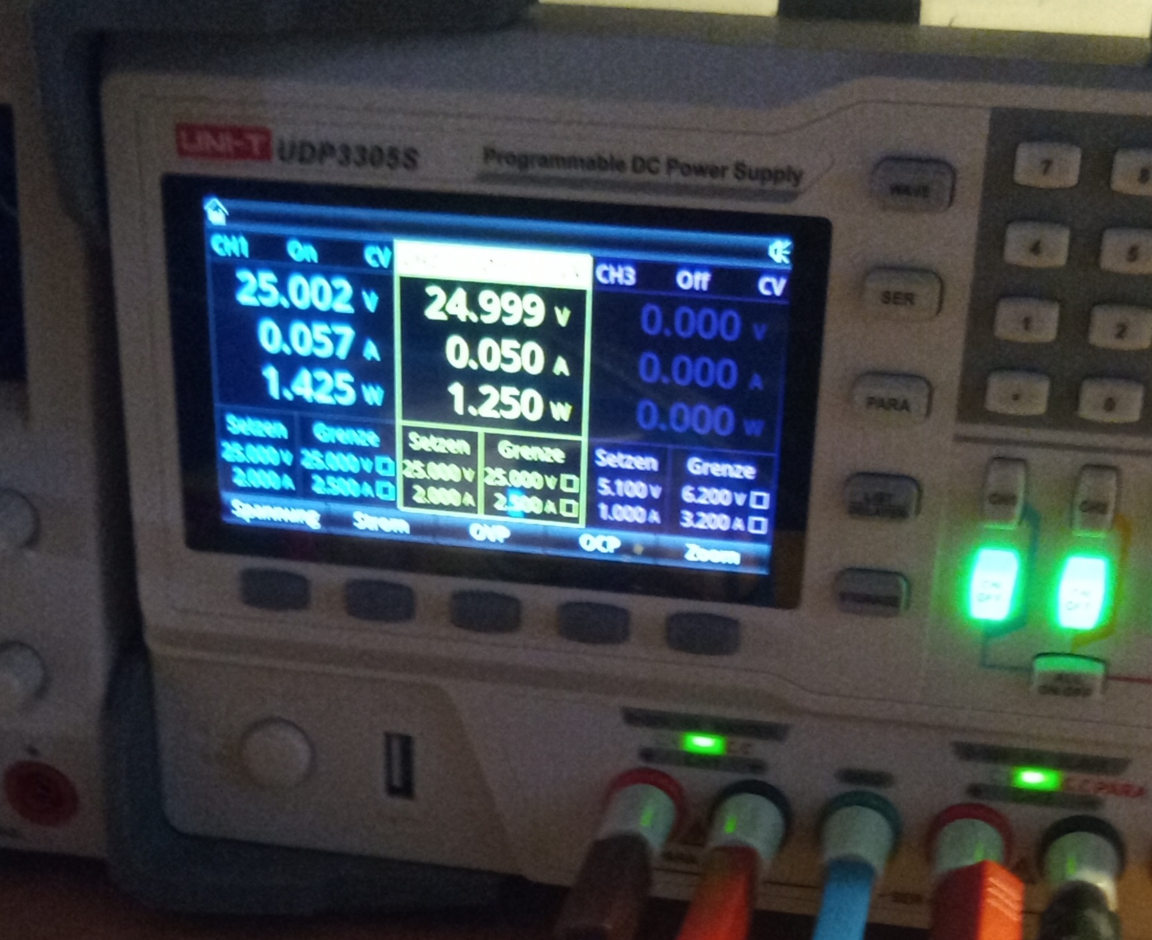
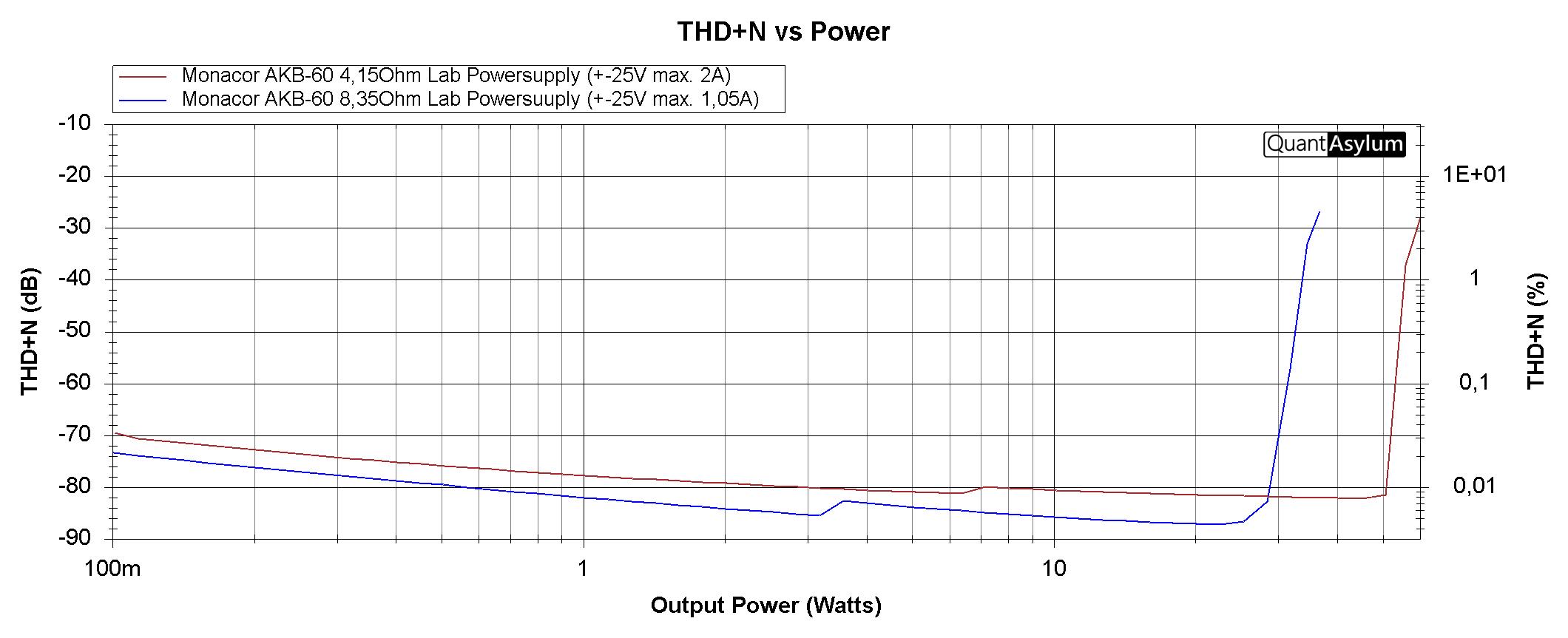
Test this Day my QA451B with 2 Amps and got good Results and also i guess found an Bug, not sure.
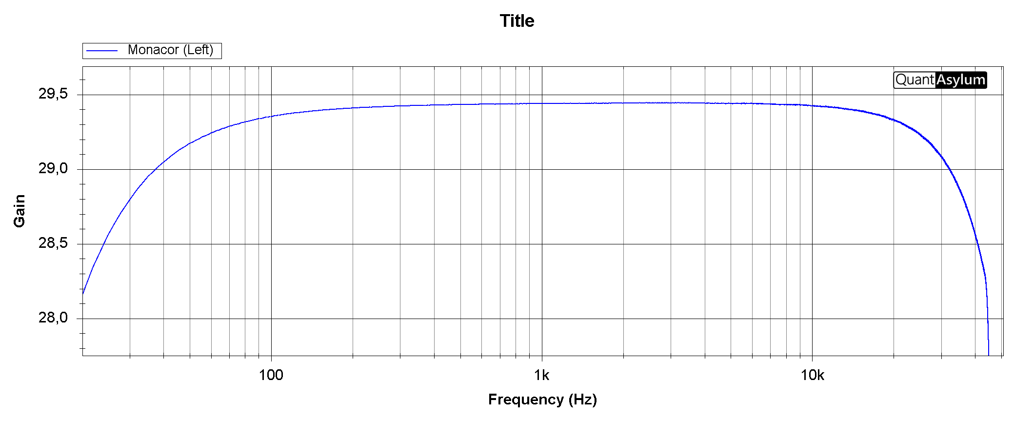
First THD+N for MONACOR AKB-60 (45Watt amp not Moded)
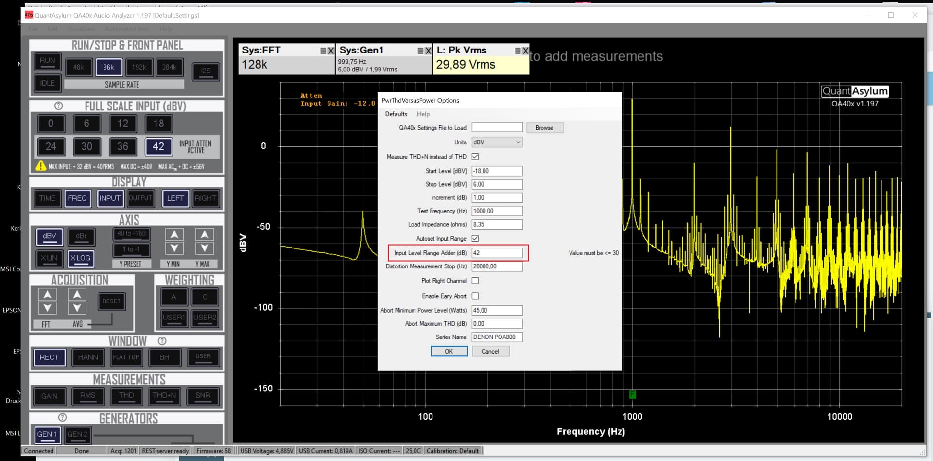
If i start the Automated Mesurement PWRTHDvsPower i need to type a value @ this field:
Input Level Range Adder (dB)
But if i want to use the Full range let say at 42dB and try to type 42 there
he dont start the Measuring and give me advice to not type more than 30dB there ??? Why???
Hi. That field is not related to the input attenuator setting value, but to the value to be added so that the input attenuator (which in this test is handled automatically since “Autoset Input Range” is selected) maintains the distance of that value in dB from the signal produced by the amplifier on the load.
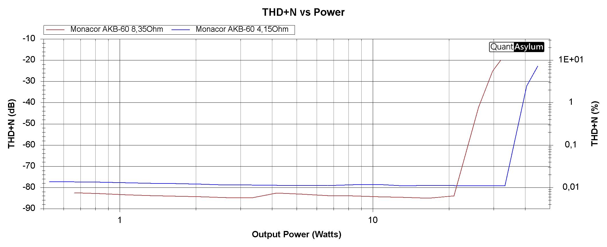
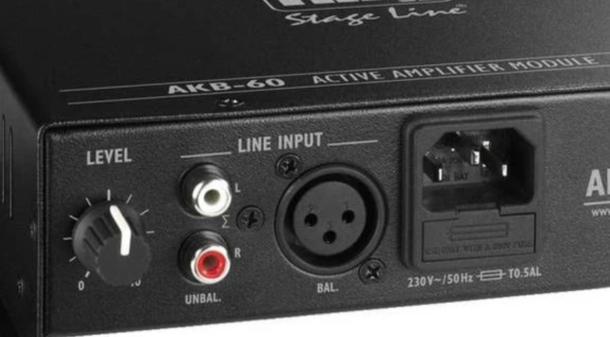
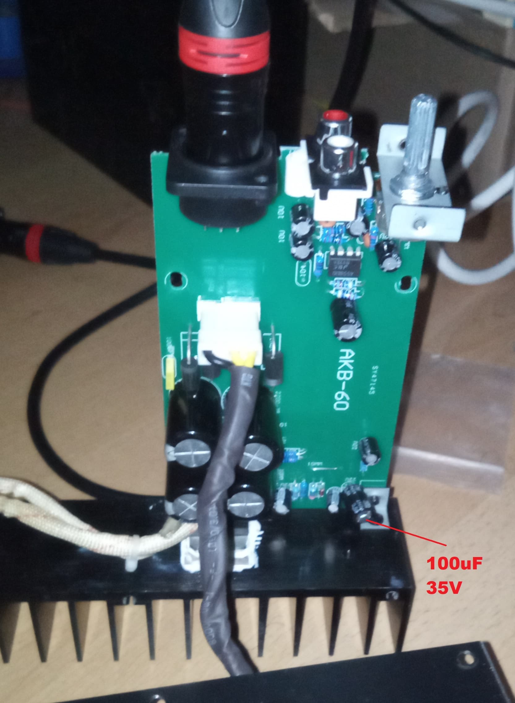
The AKB-60 has an TDA7294 in, so an well known Device.
But the Resistors get really fast Hot to 60° for this Measuring and switched off automaticaly!
You can see it on the red Trace the last Measurpoint the Load was already OFF.
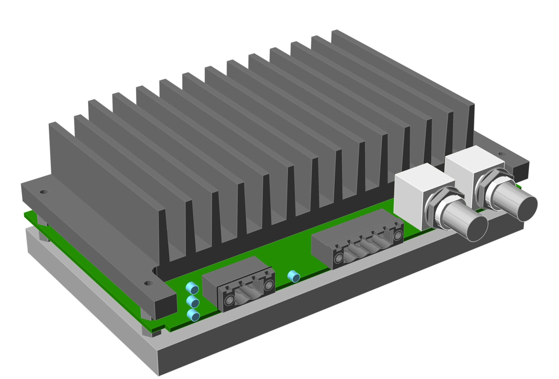
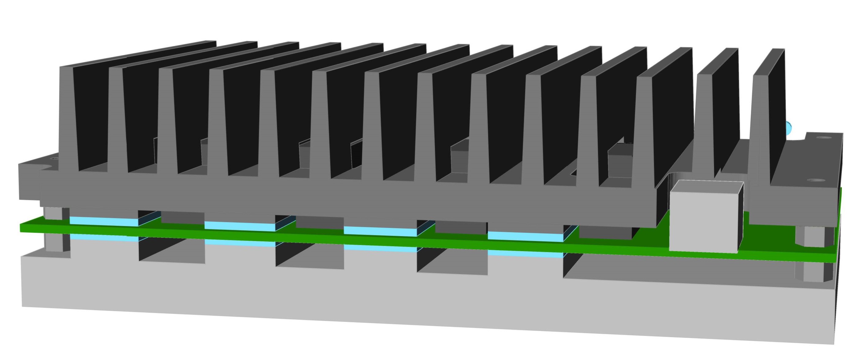
Anyway i will move it in an other Enclousure may be i can add some Thermal Pads and a nice Aluminium Heatsink from both Side to get some more seconds of running Time
The whole Enclousure is from Alluminium so may be it is enough to conect the topp and bottom of the PCB (with Thermal Pads) to the Enclousure
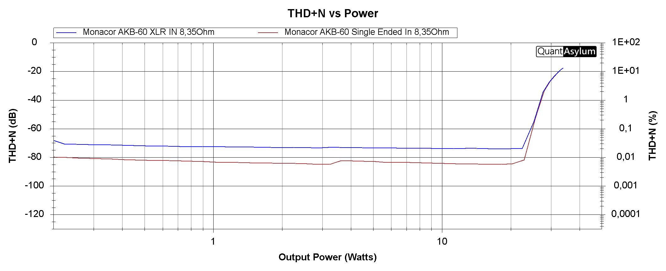
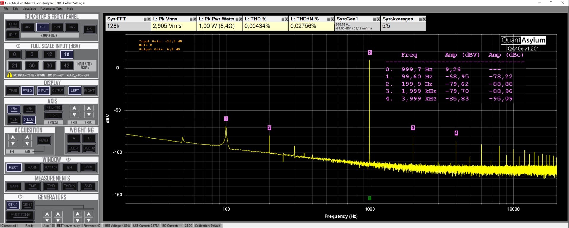
After building me an XLR to BNC Adapter i was able to make an Compare on the Monacore Amp between Single Ended and XLR Input with an little Suprise, but may be i am doing something wrong!?
XLR seems to be 10dB in THD+N Worse than Single Ended but i was sugesting it will be better ???
One Question: i get 6dB More Output Level on XLR right?
I setup the Input to -12dB and the Output to -6dB but not sure if i doing right.
I guess +6dB would be better but this don’t changed the THD+N value in General.
Also getting an Errormassage after the Measuring ands and the Value adds to the Graph’s.
But cant see where the Overload happen ??? I used the External Resistor Load!
Hi. The fact that you are using external resistors has nothing to do with the overload that is occurring on the amplifier. You are probably using an input signal to the amplifier (DUT) that is overloading it. If I may take the liberty of giving you some advice: read the QA403 manual that will help you a lot. You can find it in “Help” “Open User’s Manual PDF”
What i am not understand is the Attenuator is at 30dBV and PK VRMS was max @ 14,61 Vrms.
@ 30dBV you can Measure till 31Vrms on QA403 Imputs so how this could be an Overload?
QA403 Output has 500 mvRMS so is this Error related to QA403 Inputs or to the Amp Inputs?
I will Check the Manual but i guess this Erro is measument dependent so i need to look @ QA Wiki for this kind of Measuring.
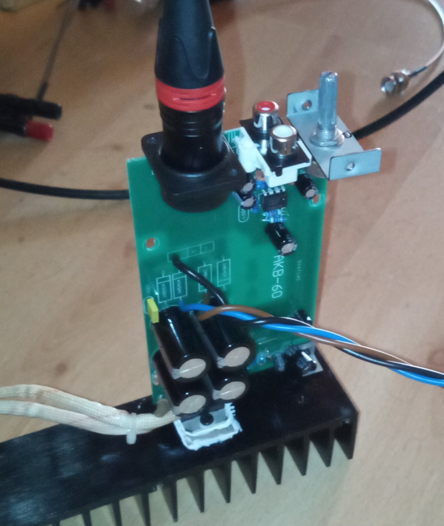
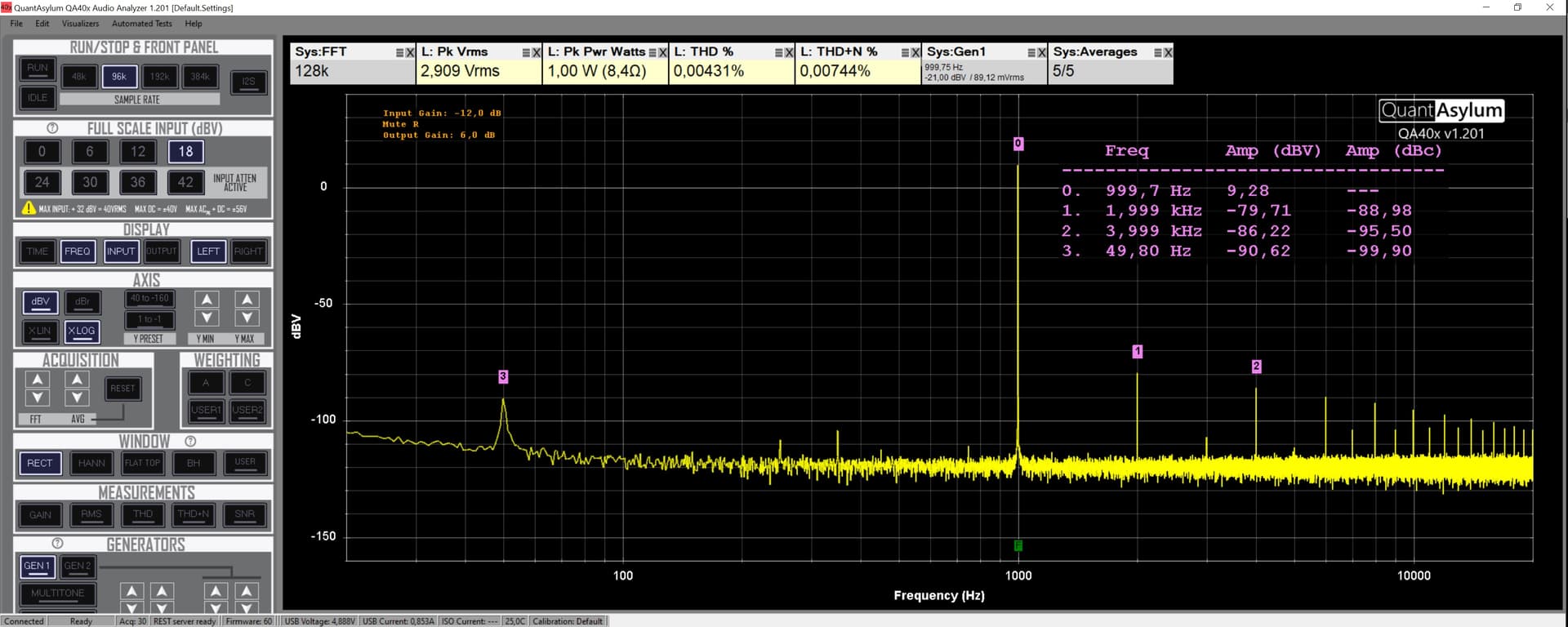
@ same Power (1Watt 8,35Ohm) the Differential looks also worse on the lower Side off 1kHz Signal (i guess an Design error or because the XLR Conector are directly next to Mains Conector, that i would never build ilke this )
THD with Mod and without Enclousure looks Better but more Noise @ THD+N i guess
But the Graph looks Cleaner may be an other Powersupply and no Diodes (NO AC) on the PCB
would help a lot. I will Change this also next.
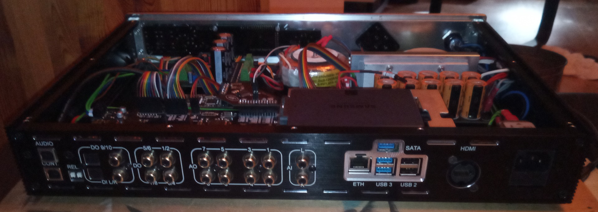
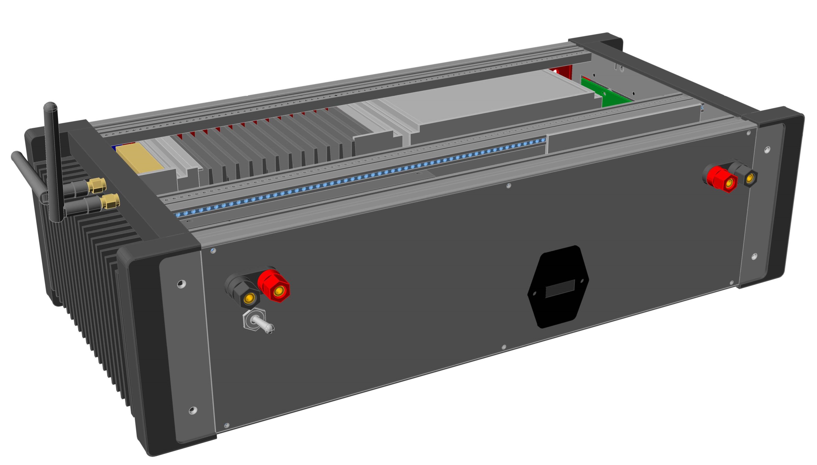
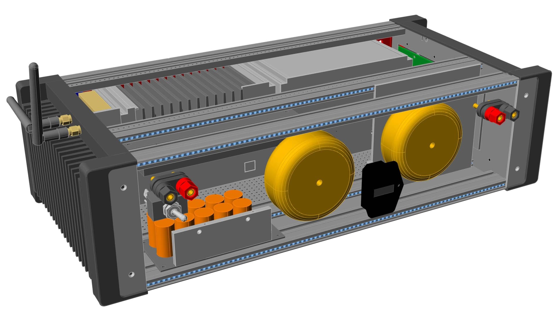
On the Left side: Battery 12V input, and Switch between Mains 12V and Battery 12V Powering.
On the Right: AMP secondary Output, Parallel to the Front.
On the Middle the Mains Connector with Mainsfiltering.